Introduction
This series of labs exposes students to introductory embedded systems concepts. The labs focus on cyber-physical systems modeling and design. They use the Lingua Franca coordination language to provide timing, concurrency, and state-machine modeling (via its modal models), and low-level programming is in C. The labs are designed to be companion exercises for a course based on Lee and Seshia, Introduction to Embedded Systems: A Cyber-Physical Systems Approach, MIT Press, 2017. The C code runs on a Raspberry Pi RP2040 on the Pololu 3pi+ 2040 robot. The same RP2040 microprocessor is also available on the low-cost Raspberry Pi Pico board, but this board does not have the sensors and actuators of the Pololu robot, so you will need the robot to be able to complete all the exercises.
Institutions Using the Labs
The embedded systems labs are used by institutions across the world for their courses in a variety of disciplines, including computer science, computer engineering, electrical engineering, and mechnical engineering. For the list of institutions using these labs, see Institutions Using the Labs.
Contributing
You can find the Markdown sources of these labs on GitHub. If you discover any problems, please consider creating an issue or submitting a pull request.
Acknowledgments
The main authors of this version of the labs are:
- Abhi Gundrala
- Hokeun Kim
- Aditya Krishnan
- Edward A. Lee
- Marten Lohstroh
These labs are derived from several generations of lab exercises for the Berkeley EECS 149/249A course, Introduction to embedded systems. Contributors to the lab design include:
- Joshua Adkins
- Prabal Dutta
- Branden Ghena
- Shromona Ghosh
- Abhi Gudrala
- Jeff C. Jensen
- Eric S. Kim
- Hokeun Kim
- Edward A. Lee
- Shaokai Lin
- Sanjit Seshia
- Trung Tran
- Matthew Weber
Prerequisites
Before getting started, please check whether you have all the necessary software installed and configured properly. Alternatively, a pre-configured Ubuntu VM image is available here. Instructions for usage of the VM are provided here.
Packages
Your system must have the following (very common) software packages installed (we recommend using your favorite package manager to install them):
gh— a CLI tool for interaction with GitHubgit— a distributed version control systemcmake— a cross-platform family of tools for building, testing and packaging softwarecode— the Visual Studio Code IDEcurl— a CLI tool and library for transfering data with URLsjava— Java 17nix— a purely functional package managerscreen— a terminal multiplexer
Installation on Ubuntu
$ sudo apt update
$ sudo apt install gh git curl openjdk-17-jdk openjdk-17-jre nix screen cmake
$ sudo snap install code --classic
Installation on macOS
$ brew install --cask visual-studio-code
$ brew install gh git cmake curl openjdk@17 screen
$ curl -L https://nixos.org/nix/install | sh
Lingua Franca Toolchain
To install the nightly (recommended) Lingua Franca CLI tools (i.e, the compiler lfc, the diagram generator lfd, and the code formatter lff), run:
curl -Ls https://install.lf-lang.org | bash -s nightly cli
If you prefer an Eclipse-based IDE over the Lingua Franca VS Code extension, install the nightly build of epoch using the following command:
curl -Ls https://install.lf-lang.org | bash -s nightly epoch
Troubleshooting for permission denied error
If you get a permission denied error while running the command above (the error will look like below):
> Creating directory /usr/local/share/lingua-franca
mkdir: /usr/local/share/lingua-franca: Permission denied
Try running the following commands which download the installation shell script and run the script with sudo:
wget https://raw.githubusercontent.com/lf-lang/installation/main/install.sh
chmod +x install.sh
sudo bash install.sh nightly cli
VS Code extensions
Please ensure that you have the following extensions installed:
ms-vscode.cmake-tools— Extended CMake support in Visual Studio Codems-vscode.cpptools— C/C++ IntelliSense, debugging, and code browsinglf-lang.vscode-lingua-franca— Lingua Franca for Visual Studio Code
For debugging support in VS Code:
marus25.cortex-debug— ARM Cortex-M GDB Debugger support for VSCode
To install them from the command line, run:
$ code --install-extension ms-vscode.cmake-tools
$ code --install-extension ms-vscode.cpptools
$ code --install-extension lf-lang.vscode-lingua-franca --pre-release
$ code --install-extension marus25.cortex-debug
Permissions
Using nix on Linux/Windows Subsystem for Linux (WSL)
To use nix on Linux, make sure that your user is a member of the nix-users group. To check this, run:
$ groups
If nix-users is not listed, run:
$ sudo usermod -aG nix-users $USER
Please note that you might need to reboot your system after running usermod in order for the new group membership to be reflected.
Using picotool on Linux/WSL
To allow access to the RP2040 via USB without superuser privileges, add custom udev rules using the following command:
$ curl -s https://raw.githubusercontent.com/raspberrypi/picotool/master/udev/60-picotool.rules | sudo tee -a /etc/udev/rules.d/60-picotool.rules >/dev/null
Getting Started
Before getting started, please make sure you have satisfied all the prerequisites.
Set up GitHub account and SSH key
If you do not yet have a GitHub account, create one.
Set up authentication with GitHub
If you haven't already, set up authentication with GitHub. The recommended way of doing this is using gh, the GitHub CLI tool. Run the following command:
$ gh auth login
Then select > GitHub.com and HTTPS if you prefer to authenticate via HTTPS, or SSH if you prefer to authenticate via SSH. The former uses a token and the latter uses a public/private key pair that it installs as part of the login procedure. After agreeing to authenticate Git with your GitHub credentials, select Login with a web browser, copy the one-time code printed on the command prompt, and press Enter. You will then be taken to github.com in your browser. After entering your credentials and pasting the one-time code, authentication will be completed.
Create your repository
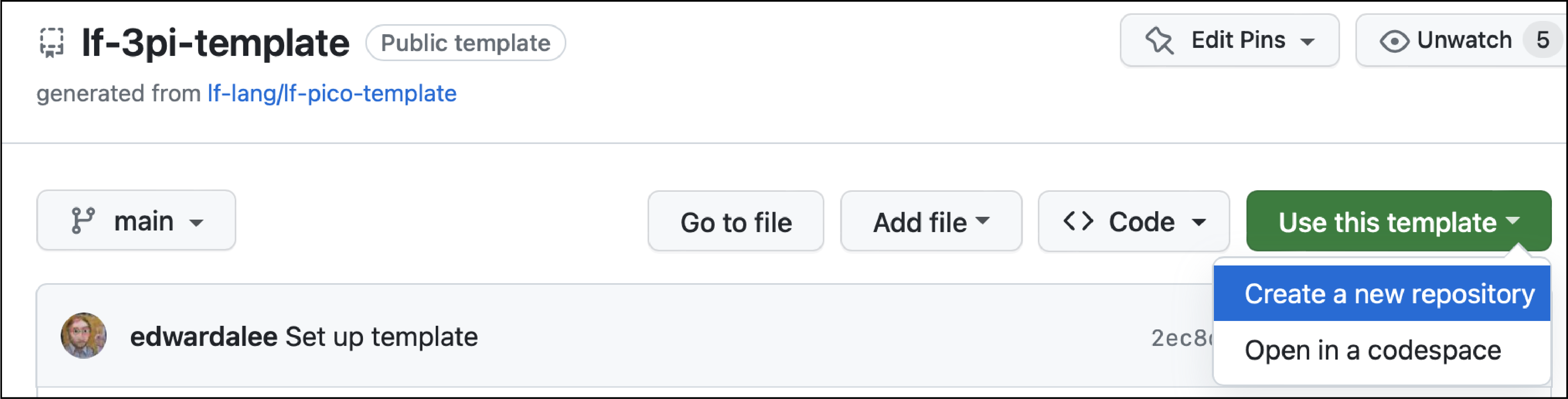
Start by creating a new private repository on GitHub based on the lf-3pi-template repository, which provides a starting point for students to carry out the exercises in this lab and to develop further applications using the Raspberry Pi Pico board and the Pololu 3pi+ 2040 robot.
Navigate to the lf-3pi-template repository. Select "Use this template" and "Create a new repository", as shown here:
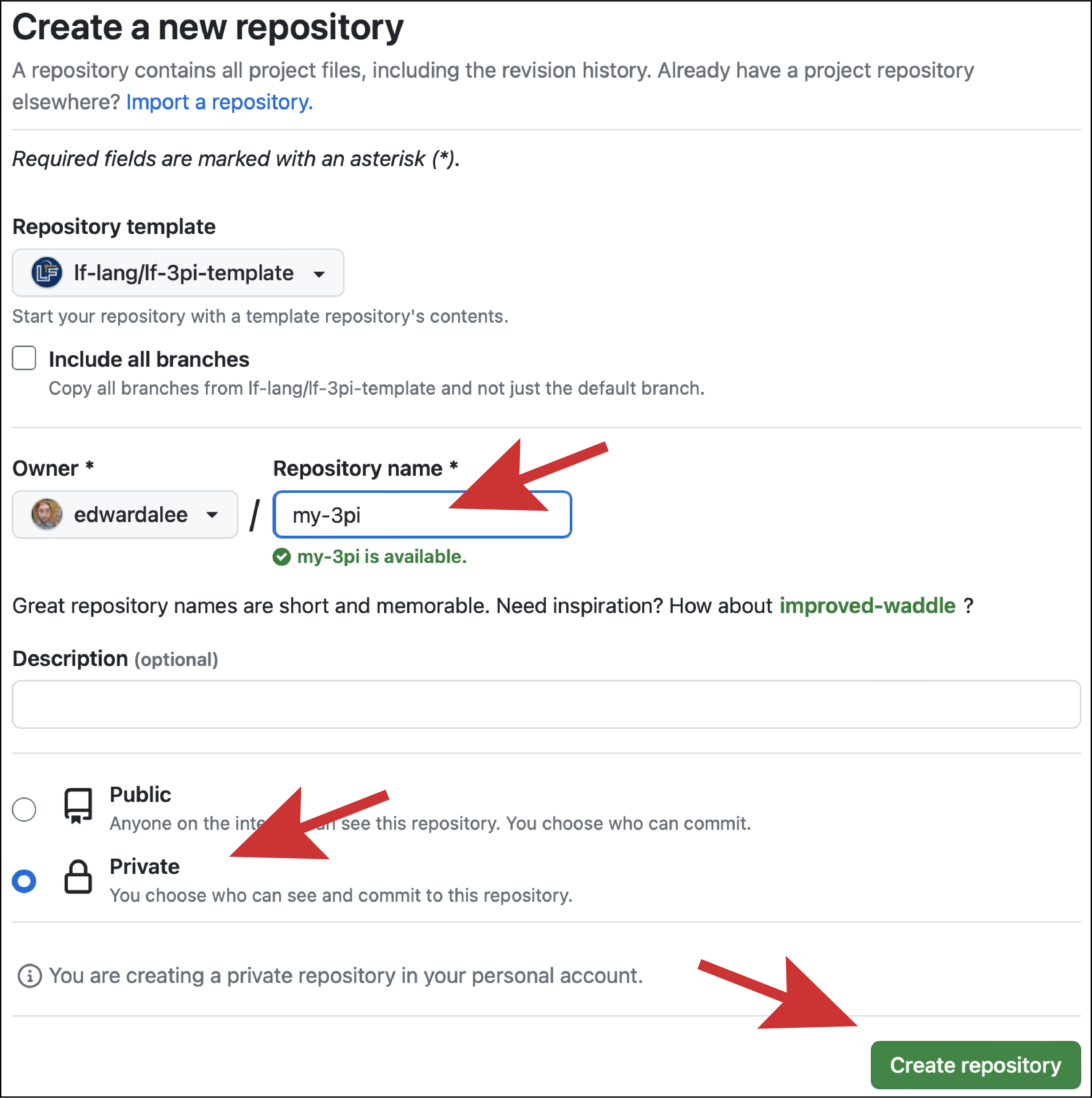
Give your repo a name and click on "Create repository":
Clone your repository
On the command line on your host machine, change directory to the location where you would like to check out your repository. Let us assume that you named your repo my-3pi. Check it out using the following command (where <username> must be substituted with your GitHub username):
$ gh repo clone <username>/my-3pi
This will create a directory called my-3pi in the current working directory.
Note for existing GitHub users
If you are an existing GitHub user and have already set up a public/private key pair (or have done so by selecting
SSHas the protocol when runninggh auth login), you can also clone the repo as follows:$ git clone git@github.com/<username>/<reponame>.git
Troubleshooting (Unknown Key Fingerprint)
If you are using the SSH protocol, then
gh repo clonemay report something like:The authenticity of host 'github.com (...)' cannot be established.and prompt you to with the following question:
Are you sure you want to continue connecting (yes/no)?The reason for this is that the key used by
github.comis not yet known by your machine. Once you typeyesand Enter, the fingerprint of GitHub's public key will be added to~/.ssh/known_hosts. Only when GitHub changes its public key will this warning reappear. This feature of SSH is meant to avoid man-in-the-middle attacks.
Note for VM users If you are using the VM image, you can skip the subsequent step; you do not have to update or initialize the
pico-sdksubmodule in your repository because it is already present in~/pico-sdk.
The template includes raspberrypi/pico-sdk as a submodule, which itself also has a lot of submodules. We recommend against using the --recursive flag because we do not need to recursively clone the submodules inside of pico-sdk. Instead, change directory into the root of your clone and run:
$ git submodule update --init
If pico-sdk was checked out correctly running git submodule in the root of the repository will show the hash without a - preceding it,
e.g.: a1438dff1d38bd9c65dbd693f0e5db4b9ae91779 pico-sdk (2.2.0).
Configure Nix
Note for VM users
If you are using the VM image, you can skip this step. You will never have to invoke
nixand can ignore any reminders about doing this.
To create a reproducible unix shell environment that installs all required dependency applications, we use the nix package manager, which has support for Linux, macOS, and Windows (via WSL). See prerequisites for installation instructions. If you prefer to manage dependencies yourself and not rely on nix, follow the instructions for a non-nix setup.
After installation, run the following in the shell to enable the experimental nix flakes feature, which helps to create more consistent builds:
$ mkdir -p ~/.config/nix
$ echo "experimental-features = nix-command flakes" >> ~/.config/nix/nix.conf
To install the dependencies, run the following in the root of your repository:
$ nix develop
This should automatically download and install specific revisions of the gcc-arm toolchain, openocd, and picotool. These packages will be required compiling, flashing and debugging C code for the RP2040.
(You can alternatively manually install the Raspberry Pi Pico Tools.)
If you hit any error while running nix develop, see troubleshooting instructions below.
Troubleshooting (Linux/WSL)
You may see an error message like this when running the
nix developcommand:error: … while fetching the input 'git+file:///home/osboxes/lf-lang/my-3pi' error: cannot connect to socket at '/nix/var/nix/daemon-socket/socket': Permission deniedThis means that your user is not a member of the
nix-usersgroup. To fix this, see prerequisites.
Troubleshooting (ARM/Apple Silicon Mac)
As of August 1, 2023, the stable version of nix does not support ARM/Apple Silicon Macs. You may see an error message like this when running the
nix developcommand:is not available on the requested hostPlatformYou can work around this issue by setting up an environmental variable and running the nix command with an additional argument,
--impure, like this:$ export NIXPKGS_ALLOW_UNSUPPORTED_SYSTEM=1 $ nix develop --impure
3. Tools and Environments
The purpose of this lab exercise is to familiarize you with the hardware and software used for embedded software programming. This lab exercise assumes you have followed the installation instructions. The Documentation and Acronyms pages will also prove particularly useful.
Embedded systems often have limited resources and interaction methods and hence require a different approach for programming. Their microprocessors often have no operating system, and are therefore called "bare metal" or "bare iron" machines. They often have no keyboard or display connected to them, which can make debugging your programs challenging. And they often have limited networking capability. These lab exercises will help you develop the capability to build sophisticated programs for such embedded systems.
In this lab exercise, you will learn to interact with a particular microcontroller, a Raspberry Pi RP2040 on the Pololu 3pi+ 2040 robot. The RP2040 microcontroller is a low cost dual-core chip designed by the Raspberry Pi Foundation in association with Broadcom. Each core implements the ARM Cortex-M0+ instruction set and is clocked at 133 MHz. The same RP2040 microprocessor is also available on the low-cost Raspberry Pi Pico board, but this board does not have the sensors and actuators of the Pololu robot, so you will need the robot to be able to complete all the exercises. See the Raspberry Pi Wikipedia page for more background on this family of microcontrollers.
Hardware
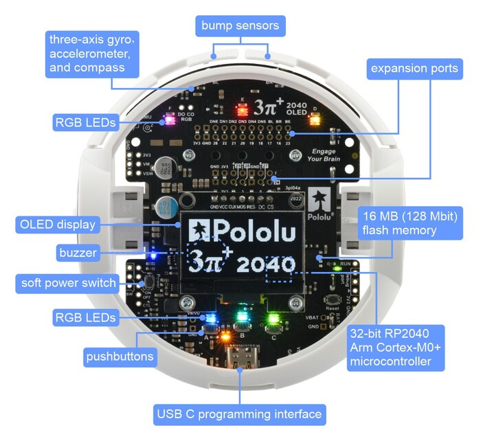
The Pololu 3pi+ 2040 robot looks like this from the top and bottom:
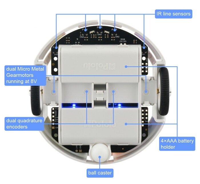
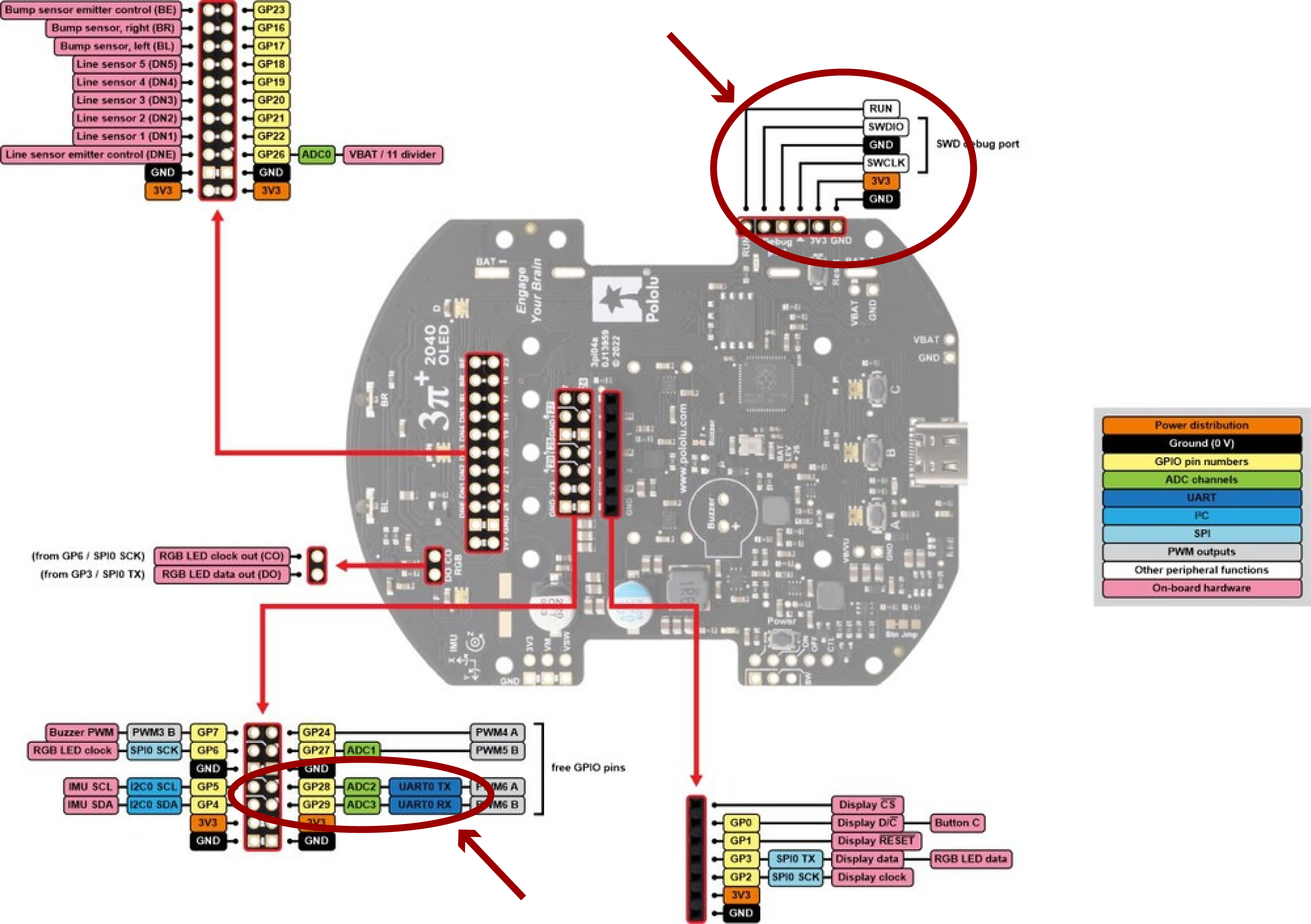
The robot is designed to be extended with additional hardware. The available electrical interfaces are shown below:
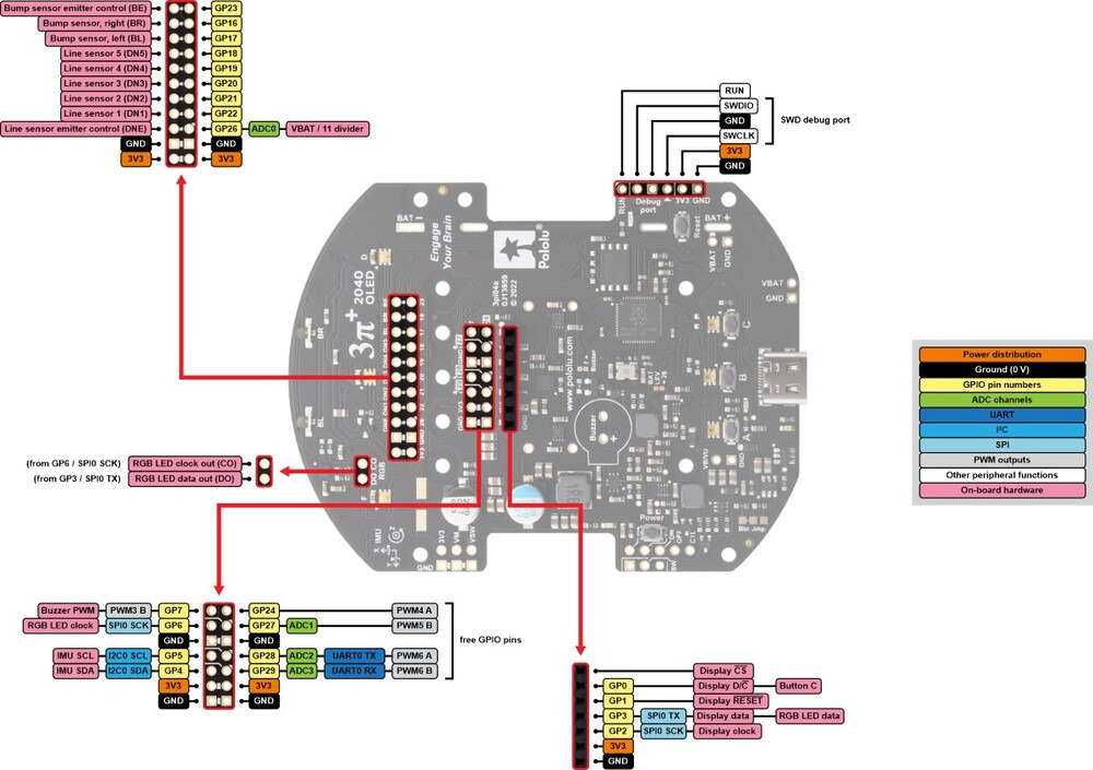
The pins GP24, GP27, GP28, and GP29 are free I/O pins that are not used for anything on the 3pi+ 2040. Each of these pins is accessible on the mid expansion header, and can be used as a general purpose input, digital output, or PWM output. Three of the pins (GP27, GP28, and GP29) can be used as analog inputs.
Software
The robot can be programmed in Python (using MicroPython) or in C. In these lab exercises, we will be programming in C to gain more direct experience with the boundary between software and hardware. The robot runs no operating system, so when you load a C program onto it, that is the only software running.
As is typical in embedded software development, the software you will write will depend on one or more layers of toolkits provided by the various companies involved in the product:
- The lowest level is the ARM Cortex-M0+ instruction set, which you will not use directly in these labs. To use it directly, you would write your code in the ARMv6 assembly language.
- The next level is to use the C language together with a cross compiler provided by ARM, Ltd. A cross compiler is a compiler that runs on a host machine (a Windows, Mac, or Linux machine) and produces machine code to be loaded onto the microcontroller. Writing programs in C is much easier than in assembly language.
- The Raspberry Pi Pico SDK is a collection of C functions designed for use with the RP2040 on the Pico board. Although the robot is not identical to the Pico board, many of these C functions work unchanged with the robot. Moreover, the develpment toolchain we will use is the same (cmake for building and picotool for loading onto the processor).
- The Robot library provided by Pololu provides additional C functions that are customized to the particular board design on the robot. These functions provide convenient interfaces to the various sensors and actuators on the robot.
- Lingua Franca is a coordination language for designing and composing software components. In these lab exercises, we will use its C target and a small library of pre-defined components called reactors that offer convenient access to certain robot features and examples on which you can base your own code.
- CMake is a build tool that manages dependencies. Nearly any program you build will depend on other programs and libraries and maintaining these dependencies can be very tedious. CMake supports encoding the dependencies in a way that makes it more likely that your code will compile even when put on a different computer or with a different filesystem organization.
Development Tools
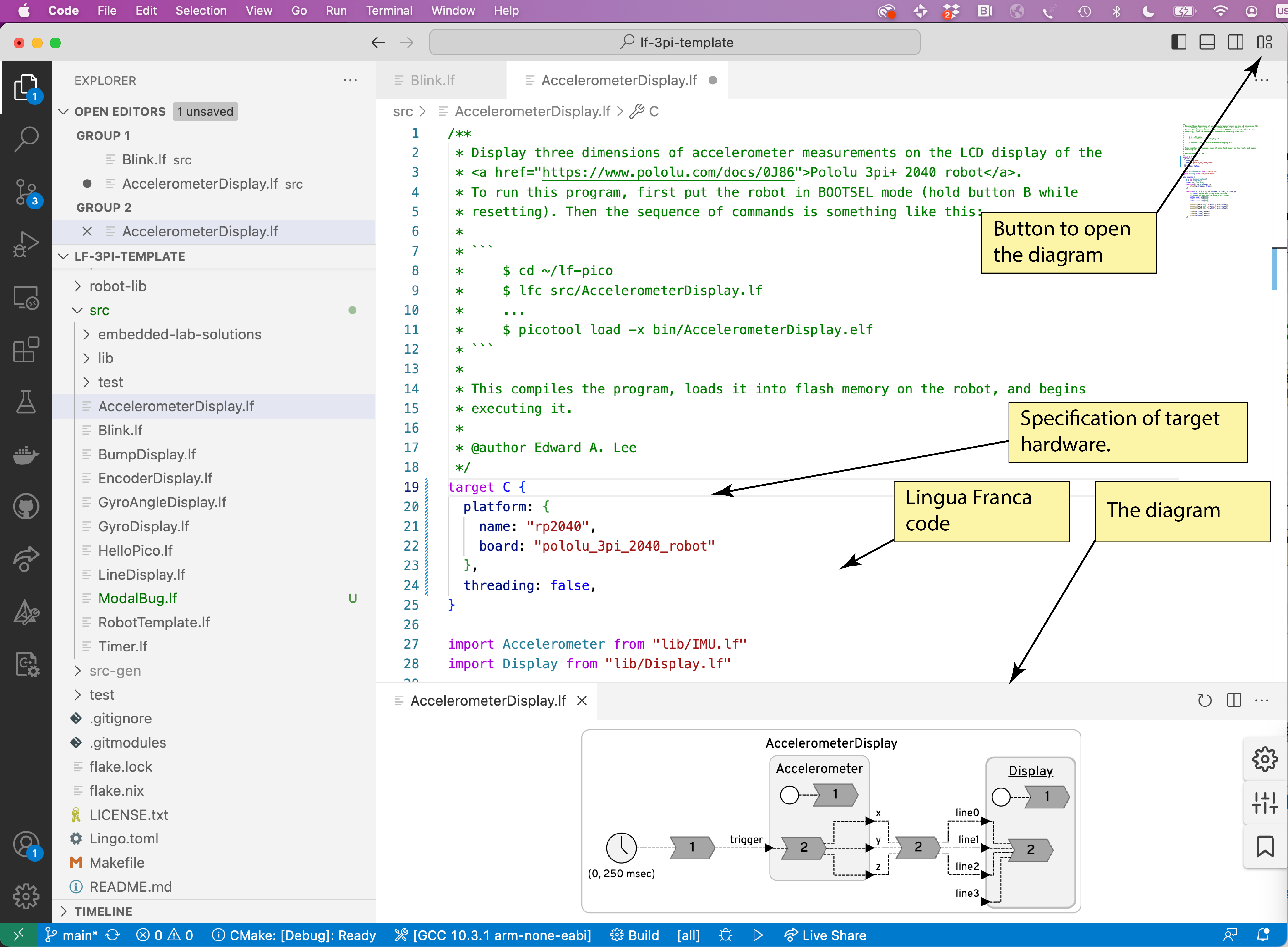
For developing C and Lingua Franca programs, we recommend using Visual Studio Code (VS Code), an integrated development environment (IDE) from Microsoft. Three VS Code extensions will prove particularly useful, the C/C++ extension, the Lingua Franca extension, and CMake Tools, all available from the Visual Studio Marketplace. The VS Code extension for Lingua Franca has a particularly useful feature where it automatically generates a diagram showing the structure of your program, as shown below:
3.1 Prelab
These exercises are intended to make sure you are up-to-speed on using the Unix command line. See Resources for some pointers.
- What flag for
lsdisplays all files, even hidden ones? - How do you move to the parent directory of the current one?
- What is the difference between the
mvandcpcommands? - What does the
-hflag oflsdo? Hint: usemanto find out. - In a git repository, what command displays whether there are any local changes and what they are?
- In a git repository, what does
git pulldo?
3.2 Deploying Example Code
We will now compile and load an example C program onto the robot. We do this two different ways, using the command line and using an IDE.
Important
If you let Nix manage your build environment, you need to always make sure to run
nix developat the root of your repository before using the shell. Besides installing things in the filesystem, it also sets environment variables likePICO_SDK_PATH, which must be set in order to compile code that uses the RPi-Pico SDK.
Ensure that your shell environment is set up correctly by checking that the PICO_SDK_PATH variable points to the root location of the RPi-Pico SDK.
You may wish to look at the README file in that directory.
Check the environment variable by printing it:
$ echo $PICO_SDK_PATH
It should print a path that looks like <path_to_your_repo>/pico-sdk.
If the environment variable PICO_SDK_PATH is not set, simply run nix develop.
Using the Command Line
First, clone the raspberry-pi/pico-examples repository (for example, in your home directory) and make it your current working directory:
$ cd ~
$ git clone https://github.com/raspberrypi/pico-examples.git
$ cd pico-examples
Make a blank build directory and use it to compile all the examples:
$ mkdir build
$ cd build
$ cmake ../
$ make
This should result in a rather lengthy output.
When it finally finishes, each of the subdirectories of the build directory will contain binary files that you can load onto the robot.
Connect the robot to the USB port of your host computer.
Before flashing the binary to your RP2040 based board, the board must be placed into BOOTSEL mode. On the Pololu 3Pi+ robot, hold the B button, press and release RESET, then release the B button.
(On a Raspberry Pi Pico, hold the RESET button while connecting the board to the host.)
You can then use the picotool to load and execute one of the sample programs:
$ picotool load -x blink/blink.elf
The -x option directs the robot to execute the code after loading it.
This will result in an LED blinking on the robot.
The loaded code will persist on the robot until the next time it is put in BOOTSEL mode and loaded with a new program.
You can disconnect the robot and use the power button to start it running on battery power.
Note
When you put the robot in
BOOTSELmode, you should see the OLED display go blank and an external disk appear with a name likeRPI-RP2. You can also deploy theblinkdemo by draggingblink.uf2(in~/pico-examples/build/blink) into theRPI-RP2folder. The robot should immediately start running the program.
Troubleshooting
You may see the following error message reported by
picotool:Device at bus 2, address 5 appears to be a RP2040 device in BOOTSEL mode, but picotool was unable to connect. Maybe try 'sudo' or check your permissions.If you see this message, this means that your user does not have permission to access the RP2040 via USB. You can add
udevrules to allow regular users to access the RP2040, as described here.
For WSL users,usbipdneeds to be installed and used with Windows PowerShell as an administrator. Please check here for more details.
Using VS Code
Next we will repeat the exercise, but this time using VS Code rather than the command line to compile the code. Under the hood, VS Code uses the CMake Tools extension to achieve the same process.
Start VS Code in your root pico-examples directory:
$ cd ~/pico-examples
$ nix develop
$ code .
(The second line may not be necessary if you have already done this.)
This will likely result in a popup appearing as follows:
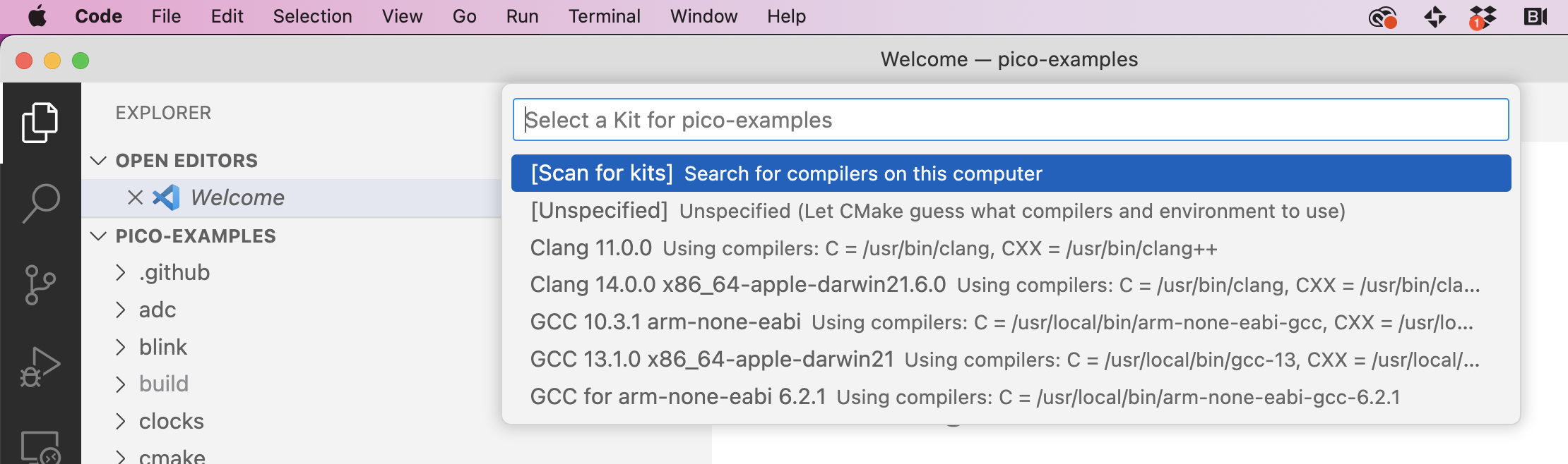
You should select the arm-none-eabi kit. If you do not see one, select "Scan for kits". It you do not see the popup above, click on "No kit selected" on bottom bar. NOTE: You may need to make sure that CMake Tools is the Configuration Provider. Select View > Command Palette in the menu (or use the keyboard shortcut Shift + Ctrl + P on Linux/Windows; Shift + Cmd + P on a Mac) and begin typing C/C++ Change Configuration Provider until you see this:
NOTE You may need to make sure that CMake Tools is the Configuration Provider. Select View > Command Palette in the menu and begin typing C/C++ Change Configuration Provider until you see this:
If CMake Tools is not available, then the cmake extension is not installed in VS Code.
Note for VM users If you are using the VM image, click on "No kit selected" and you should be able to find the
arm-non-eabikit in the drop-down menu. You might also be unable to find theCMake Tools (active)as above, but compilation should still work.
If all goes well, VS Code will have configured and generated all the build files, and you see output something like this:
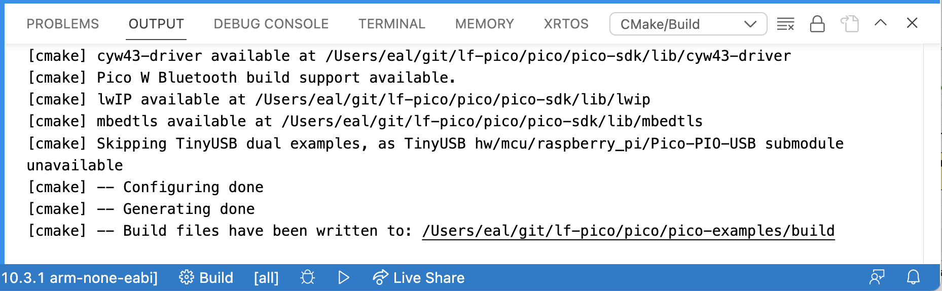
VS Code has run CMake, but it has not yet compiled the example programs. To compile them, click on the "Build" button in the blue bar at the bottom. If you already ran the build on the command line as above, then this time it should not take too long.
When you see "Build finished with exit code 0," then you can load the code onto the robot using picotool. To do this from within VS Code, select the Terminal tab in the Output subwindow and issue the load command as above:
$ picotool load -x build/blink/blink.elf
Make sure the robot is in BOOTSEL mode before doing this.
Examining the C Program
Find and examine the C program blink.c. How is it controlling the timing of the blinking of the LED?
Checkoff: Verify that the VS Code and command-line mechanisms are working. Explain how the timing of the blinking of the LED is controlled.
3.3 A First Lingua Franca Program
Start code in the root of your repository based on lf-3pi-template (see Getting Started):
$ cd ~/my-rpi3
$ code .
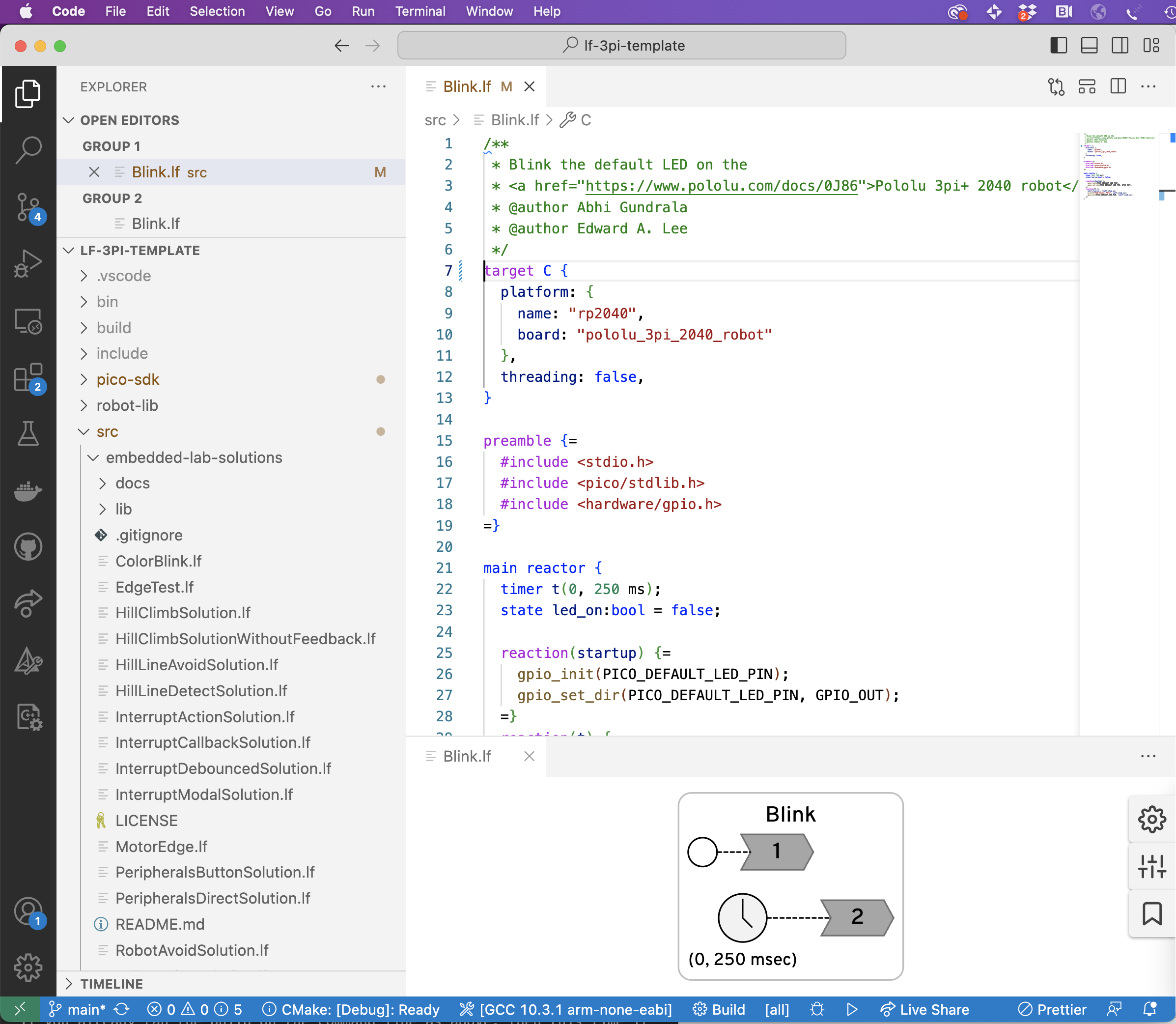
Open and examine the Blink.lf program in the src directory. You may want to open the diagram and drag its window pane to the bottom so that you see something like this:
To compile this program, use Ctrl + Shift + P and select the option Lingua Franca: Build (start typing until auto-complete finds it). On a Mac, use the Cmd key instead of Ctrl.
Alternatively, you could use lfc to invoke the compiler from the command line. You can do this from a terminal outside VS Code, or by selecting View > Terminal from the menu, and typing:
$ lfc src/Blink.lf
Connect your robot in BOOTSEL mode and load and execute the program:
$ picotool load -x bin/Blink.elf
You should see same blinking LED as before.
Now, examine the LF program. How is the timing of the LED controlled here? You may want to consult the Lingua Franca documentation for timers.
Modify the Blink.lf program to use two timers, one that turns on the LED and one that turns it off, eliminating the state variable led_on.
Put your modified program in a file called ToolsBlinkSolution.lf.
Checkoff: Show your modified LF program. Explain how this use of timers is different from the sleep function used in the C code blink.c.
3.4 Printing Output
As is typical of embedded platforms, the Pololu robot does not normally have a terminal connected to it. The LEDs and small LCD display can be used to get information about the running program, but often, particularly while debugging, it is convenient to be able to simply insert printf statements into your programs to see what is going on.
Your first task here is to modify your previous LED blinker to print "ON" and "OFF" each time it turns on or off the LED.
Please put your modified program in a file called ToolsPrintfSolution.lf.
If you run the program as above, however, where do these printed statements go?
The C function printf sends textual data to a conceptual device called stdout (for "standard output").
By default, the robot is configured to direct all stdout text to a serial port on its USB interface.
The trick, therefore, is to get your host computer to connect to that serial port and display data that arrives from the robot.
To do that, we use a terminal emulator called screen. But first, we have to identify the serial port device that was created when the program started up.
Finding the device on macOS
On macOS, the device is likely to appear in the /dev directory on your computer under a name that includes "usb" in its name, which you can look up as follows:
$ ls /dev/*usb*
The output may look like this, listing both a "callin" device /dev/tty.usb* and a "callout" device /dev/cu.usb* (for more information, see StackOverflow):
/dev/cu.usbmodem14201 /dev/tty.usbmodem14201
Finding the device on Linux
On Linux, the device is likely to appear in the /dev directory under a name that starts with ttyACM, which you can look up as follows:
$ ls /dev/ttyACM*
Note for VM users
ttyACM\*cannot be found when Pololu is in BOOTSEL mode. To find it, pressRESET, choose the USB device (in VirtualBox:Device->USB->Raspberry Pi RP2 Boot), and you should be able to see it under/dev.
Using screen
To use screen, we specify a device (e.g., /dev/ttyACM0) and a baud rate, as follows:
$ screen <device> 115200
You should now see the printed outputs. You can return terminal to normal mode by detaching screen by typing Ctrl + a followed by d. You can reattach with:
$ screen -r
To permanently end screen, type Control-A k (for kill).
If screen immediately exits with the message [screen is terminating], you might need to execute it with root rights.
Checkoff: Show ON-OFF output.
3.5 Modular Reusable Reactors
The LED code in Blink.lf is in a main reactor, which cannot be imported into any other Lingua Franca application.
Your next task is to create reusable reactor called LED that has a single input named set with type bool.
When the reactor receives an input event with value true, it should turn on the LED.
When it receives an input with value false, it should turn off the LED.
To do this, create a file in your src/lib directory called LED.lf with the following structure:
target C {
  platform: {
    name: "rp2040",
    board: "pololu_3pi_2040_robot"
  },
  single-threaded: true
}
preamble {=
  #include <hardware/gpio.h>
=}
reactor LED {
  input set:bool;

  reaction(startup) {=
    // Fill in your code here
  =}

  reaction(set) {=
    // Fill in your code here
  =}
}
Then create a new LF file called ToolsLEDSolution.lf that imports this reactor and drives its input in such a way as to blink the LED. The following LF documentation could prove useful:
You have probably noticed some patterns here. E.g., each LF file begins with this:
target C {
  platform: {
    name: "rp2040",
    board: "pololu_3pi_2040_robot"
  },
  single-threaded: true,
}
This specifies that the target language is C, so the lfc compiler generates C programs. The platform specification indicates that the C runtime system for the Raspberry Pi 2040 should be used and that the target board is the Pololu robot. The single-threaded directive indicates that the target is bare metal machine with no operating system and no thread library.
To initialize and toggle the LED, we are using library functions like gpio_put which are declared in a header file gpio.h that is part of the standard Pico SDK.
Inclusion of this header file is a consequence of this directive:
preamble {=
  #include <hardware/gpio.h>
=}
What happens if you omit this?
For documentation about this header file, see the Pico SDK documentation, and specifically the hardware_gpio section.
These functions manipulate memory-mapped registers that control the GPIO pins of the processor.
On the robot, one of those pins, identified in the header files by the PICO_DEFAULT_LED_PIN macro, controls the LED you see blinking.
Subsequent labs will explore more deeply the use memory-mapped registers for I/O.
Checkoff: Show and explain how your program works.
3.6 Postlab Questions
-
What format specifier(s) for
printfallows the printing of floats (there may be several)? -
When might
printfstatements be the best tool for debugging? -
What other tools might be useful for debugging embedded software (note that using an interactive debugger like
gdbwith the robot or Pico board is possible but requires extra hardware)? -
What does the
volatilekeyword mean in C and when might you use it? -
What were your takeaways from the lab? What did you learn during the lab? Did any results in the lab surprise you?
4. Interfacing with Sensors
The purpose of this exercise is to learn to read sensor values on a microcontroller and to interpret those values. You will read accelerometer data from a device on the Pololu robot, convert the readings to meaningful units, and use the results to estimate the tilt of the surface on which the robot sits. As a side effect, you will gain experience reading a technical datasheet.
The Pololu robot includes an inertial measurement unit (IMU) made by ST Microelectronics, part number LMS6DSO, which includes an accelerometer and a gyroscope. In this lab, we will focus on the accelerometer.
On the robot, the IMU is connected to the RPi via the I2C bus, a serial communication bus that is widely used to connect lower speed peripheral chips to microprocessor chips.
Part of the purpose of this exercise is to learn to work from incomplete documentation, an inevitable reality in any engineering project. It takes a certain amount of detective work to identify properties of the hardware you are working with that may be important in your application.
4.1 Prelab
References
- Chapter 7, Sensors and Actuators, of Lee and Seshia
- ST LMS6DSO inertial module datasheet
Questions
-
Reading a datasheet.
-
The output data rate (ODR) is determined by a register on the IMU chip called
CTRL1_XL. On the Pololu robot, theCTRL1_XLregister is set to hexadecimal value 0x30 (0b00110000 in binary) during initialization of the robot (by writing to the I2C bus). What is the ODR rate that this specifies?Hint: Section 9.12 of the inertial module datasheet describes the
CTRL1_XLaccelerometer control register. -
The accelerometer on the robot can be configured to have one of four ranges by setting the
CTRL1_XLregister. Each range is a multiple of g, the acceleration due to gravity at the earth's surface, defined to be 9.80665 m/s2. What are the ranges supported by the accelerometer on the IMU chip? -
The robot software configures the accelerometer hardware to use one of these four ranges during initialization. What is this range?
-
The IMU chip offers an optional low pass filter (LPF) that performs additional smoothing of the signal from the accelerometer at the cost of additional latency. By default, the robot initializes the IMU to not use this filter. What value would you set the
CTRL1_XLregister to to use the filter and leave the ODR and range as above?
-
-
Interpreting sensor data
-
According to table 2 of the inertial module datasheet, with the default range, the sensitivity of the accelerometer is 0.061 mg/LSB. Here, mg stands for milli-g's and LSB for least significant bit. The accelerometer has a 16-bit analog to digital converter (ADC). Reading its raw data over the I2C bus yields a 16-bit signed integer. Explain where the number 0.061 comes from.
Note: The
robot-liblibrary provides a convenience functionimu_read_accthat reads accelerometer data into an array of floats, which it converts into units of g. Hence, when using this library, you will not need to deal with the complexities of interpreting the raw binary output of the accelerometer. But understanding the sensitivity is still important. -
As explained in Chapter 7, Sensors and Actuators, of Lee and Seshia, a sensor output may be modeled by an affine function f(x) = ax + b, where a is the sensitivity and b is the bias. For this IMU, ideally, if x is the 16 bit integer received over the I2C bus, a = 0.000061, and b = 0, then f(x) is the acceleration in g's. But both a and b may vary with temperature. How much variation in a should you expect (in percent per degree centigrade)? How much bias can you expect (in mg)? How much should you expect the bias to change with temperature (in mg per degree centigrade)?
Hint: Table 2 could be helpful. Bias is referred to as "zero-g level" in this table.
-
4.2 Sampling an Accelerometer
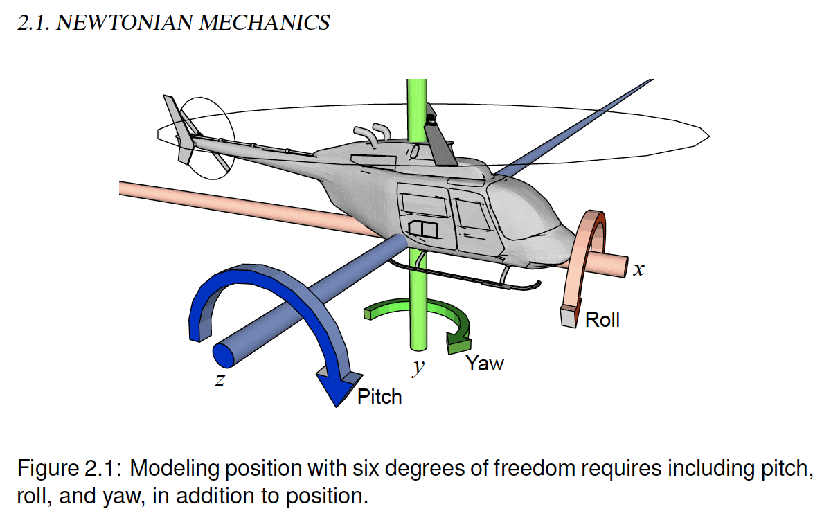
The goal of this lab is to calculate and display the inclination of the Pololu robot. The inclination is the amount of tilt of the surface on which the robot sits. Chapter 2 of Lee and Seshia describes the orientation of a vehicle in terms of pitch, roll, and yaw, illustrated as follows:
Our goal will to just measure pitch and roll because we will assume that the robot always sits right-side-up on a reasonably level surface. Our goal will be to measure relatively small deviations from level.
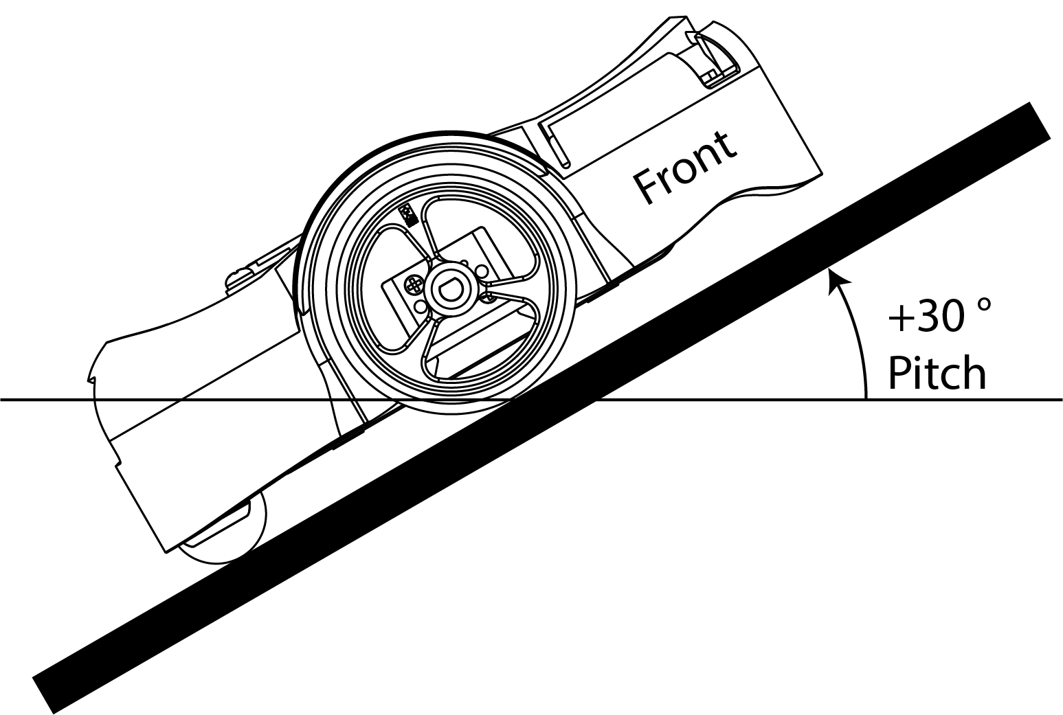
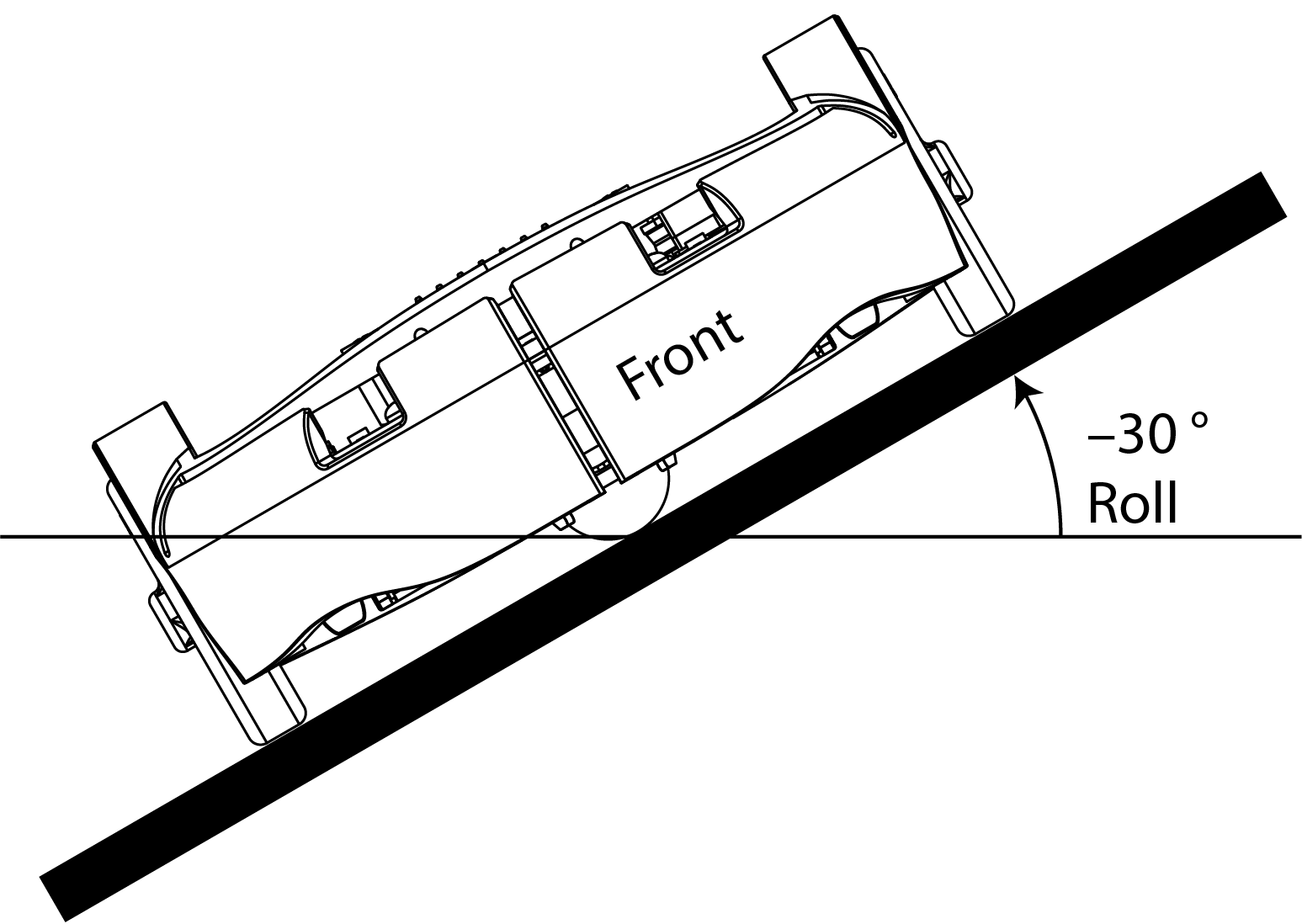
Pitch is the angle deviation from horizontal of a straight line coming out of the front of the robot. Roll is the angle deviation from horizontal of a straight line going directly through the wheels. These are illustrated in the following figures:
Note: An accelerometer cannot measure yaw because Earth's gravity acts in the same direction as the Z-axis, which prevents the accelerometer from measuring rotation on the Z-axis. Instead, a different sensor called a magnetometer (i.e., digital compass) could be used to measure yaw by measuring an object's orientation relative to Earth's magnetic north pole. (Reference: IoT Code Guidebook - Accelerometer)
It is a simple geometry problem to figure out how to calculate these two angles from accelerometer measurements. But if you are rusty on your geometry, you could consult page 7 of Using an Accelerometer for Inclination Sensing, by Christopher J. Fisher.
To help you get started, a sample Lingua Franca program AccelerometerDisplay.lf is provided. To try out the program, plug your robot into the USB port of your host computer and put it in BOOTSEL mode by holding the B button while pressing the reset button. In the root directory of your clone of the lf-pico repo, compile and load the program onto the robot:
$ lfc src/AccelerometerDisplay.lf
$ picotool load -x bin/AccelerometerDisplay.elf
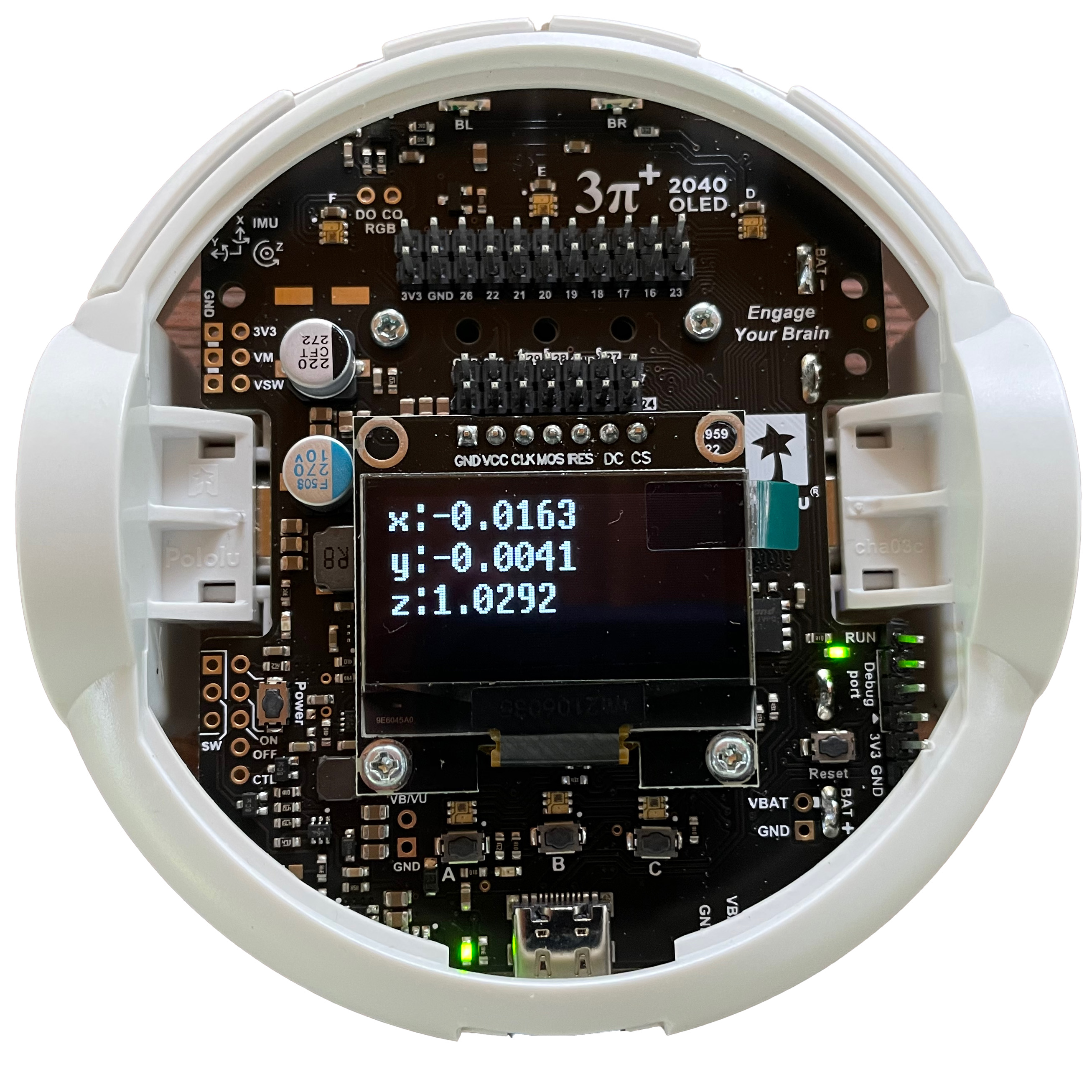
You should see the display light up looking something like this:
-
Interpreting the numbers
- Explain why, when the robot is sitting on a flat surface, the sensed accelerations in the x and y directions are near zero and in the z direction near one.
- Why is the z direction not near negative one? Doesn't gravitation pull you down, not up?
Experiment with rotating the robot and observing how the three measured accelerations change.
CHECKOFF: Demonstrate the app working on all three axes.
-
Examine the LF program
-
Open the file
src/AccelerometerDisplay.lfin VS Code. Enable the diagram, navigate and read the code, and explain what each of the reactions labeled A, B, C, and D does: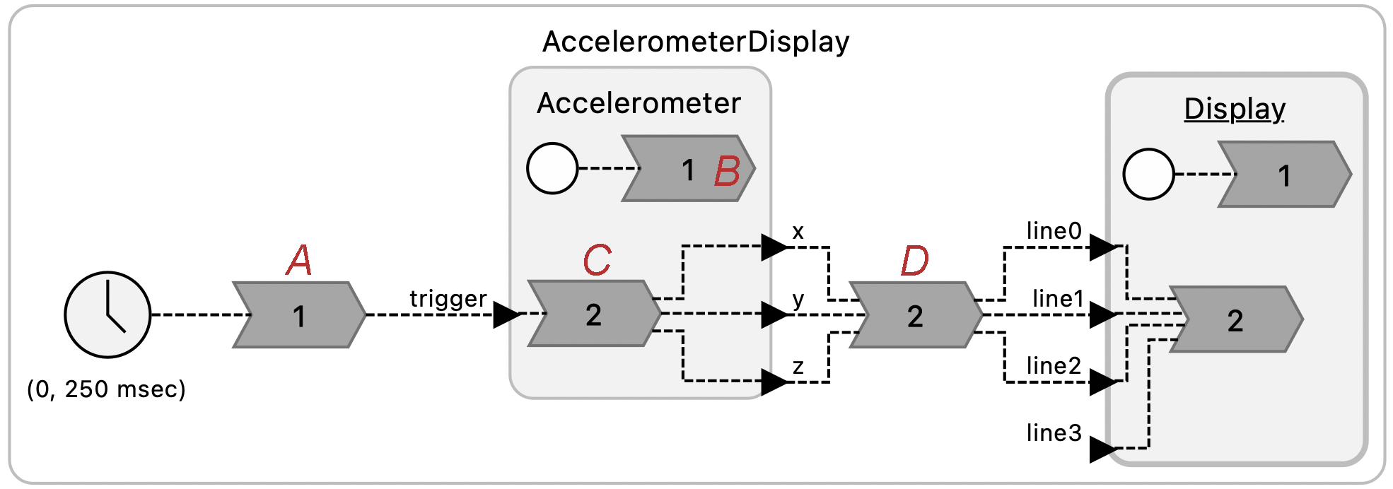
-
Notice the
targetspecification at the top of each of the .lf files. What do you think is the significance of the directive:single-threaded: true
CHECKOFF: Explain what the four reactions do and the importance of single-threaded being turned on.
-
4.3 Measuring Tilt
Create a reactor called Tilt that takes as inputs the x, y, and z readings from the accelerometer and outputs the pitch and roll in degrees. Save the file's name as Tilt.lf, and put this file in the src/lib directory and then use it in a variant of the AccelerometerDisplay.lf named SensorsTiltSolution.lf, to show pitch and roll in degrees rather than g force accelerations in the LCD display. Save your Tilt.lf file and Tilt reactor for use in future labs.
CHECKOFF: Show your pitch and roll displays and check that they are reasonable.
4.4 Postlab Questions
-
Suppose a sensor gives you a 16-bit signed integer representing some measured quantity in some well-defined units, that the range of the sensor in those units is -4.0 to 4.0, and that the sensitivity in those units is 0.000122 (1/213). What is representation in hex and in binary of a sensor reading of 1.0 in those units?
-
Suppose that your goal with the accelerometer is to measure the tilt in degrees of the surface on which your robot is moving. How would you measure the bias and then compensate for this bias?
-
Suppose that your goal is to orient the robot to point straight up the hill. How would you use the pitch and roll measurements to accomplish this?
-
What were your takeaways from the lab? What did you learn during the lab? Did any results in the lab surprise you?
5. Peripherals and Memory-Mapped I/O
The purpose of this lab exercise is to learn how sensors and actuators are connected to a microcomputer and how the memory system abstraction is used to access and control the hardware. In the previous labs, you accessed peripheral devices (an LED and an accelerometer) using GPIO and the I2C bus, respectively. In this lab, we will demystify the SDK functions that were called to access these devices.
For background, review Chapter 9 (Memory Architectures) of Lee and Seshia. The particular chip on the Pololu 3pi+ 2040 robot is a Raspberry Pi RP2040. The RP2040 Datasheet is the definitive reference for this chip. Sections 2.2 (Address Map) will be particularly useful for this lab, but the datasheet can be daunting. The source code for SDK can also be a valuable reference.
On the RP2040, peripheral devices are accessed via one of three on-chip busses called AHB (Advanced High-performance Bus), APB (Advanced Peripheral Bus), and IOPORT. APB is used for lower-speed peripherals, AHB for higher speed peripherals, and IOPORT for single-cycle I/O (SIO) peripherals, the highest speed.
5.1 Prelab
-
The I2C bus on the RP2040 is accessed by reading and writing memory addresses begining at 0x40044000. Does this use AHB, APB, or IOPORT?
Note: To determine the starting address 0x40044000, a careful reading of section 2.2, Address Map, of the RP2040 Datasheet reveals that the SDK defines a macro
I2C0_BASEwith value 0x40044000. Alternatively, you can use the search mechanism of your IDE (e.g. VS Code) to trace the source code. TheAccelerometerreactor defined in thesrc/lib/IMU.lffile invokes a function calledimu_read_acc. Searching for this function definition reveals it inrobot-lib/src/imu.c. Examining the source code reveals that it references a variablei2c0. Searching for this reveals that is a macro defined inpico-sdk/src/rp2_common/hardware_i2c/include/hardware/i2c.hthat refers toi2c0_inst, which in turn refers toi2c0_hw, which in turn refers toI2C0_BASE. Finally, that latter macro is defined inpico-sdk/src/rp2040/hardware_regs/include/hardware/regs/addressmap.has follows:#define I2C0_BASE _u(0x40044000) #define I2C1_BASE _u(0x40048000)This sort of detective work, albeit tedious, can be invaluable when determining how things actually work.
-
To understand how a program interacts with hardware, it is important to understand exactly how the C language uses pointers.
-
Which of the following code snippets reads the value of a 32-bit register at address 0x40001000 into a variable named foo?
// (1) uint32_t *load = (uint32_t) 0x40001000; uint32_t foo = load; // (2) uint32_t *load = (uint32_t *) 0x40001000; uint32_t foo = *load; // (3) uint32_t load = (uint32_t) 0x40001000; uint32_t foo = load; -
Which of the following code snippets writes the value 5 to the address 0x4000600F?
// (1)
uint32_t *store = (uint32_t *) 0x4000600F;
store = 5;

// (2)
uint32_t store = (uint32_t) 0x4000600F;
store = 5;

// (3)
uint32_t *store = (uint32_t *) 0x4000600F;
*store = 5;
-
-
The
src/Blink.lfexample provided to you calls a functiongpio_putwith two arguments,PICO_DEFAULT_LED_PIN(which has value 25 for the Pololu robot) and true or false to turn the LED on or off. That function is defined in the SDK as follows:static inline void gpio_put(uint gpio, bool value) { uint32_t mask = 1ul << gpio; if (value) gpio_set_mask(mask); else gpio_clr_mask(mask); }The functions
gpio_set_maskandgpio_clr_maskare defined as follows:static inline void gpio_set_mask(uint32_t mask) { sio_hw->gpio_set = mask; } static inline void gpio_clr_mask(uint32_t mask) { sio_hw->gpio_clr = mask; }A bit of detective work (Section 2.3.1.7, List of Registers, of the RP2040 Datasheet or writing a program that prints the values) reveals the following values:
PICO_DEFAULT_LED_PIN: 25 sio_hw: 0xd0000000 &sio_hw->gpio_set: 0xd0000014 &sio_hw->gpio_clr: 0xd0000018-
Which bus, AHB, APB, or IOPORT, is used to control the GPIO pin that turns on an off the LED?
-
Explain the role of
maskvariable ingpio_put. Why is its value the same whether you are turning on or off the LED? How does the hardware recognize whether you intend to turn on or off the LED? -
The second argument to
gpio_putspecifies whether to "set" or "clear" the GPIO pin. Setting the pin means bringing its voltage high, whereas clearing it means bringing the voltage low (to ground). The 3pi 2040 Control Board Schematic reveals that GPIO pin 25 is connected on the robot as follows: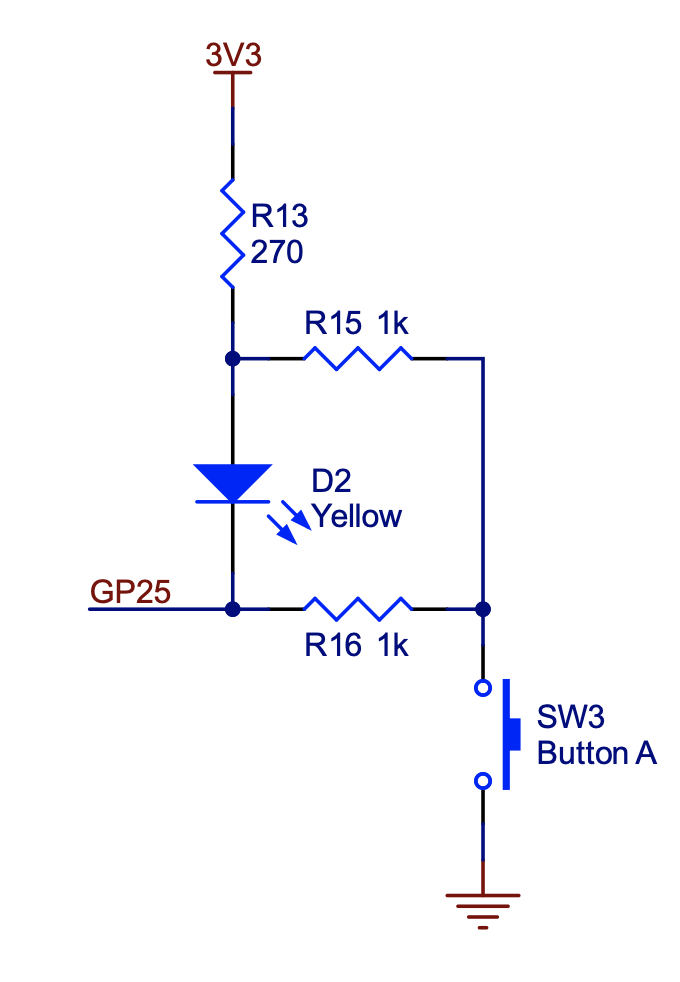
Should you set or clear the GPIO pin to turn on the LED? What do you expect will happen when you push button A?
-
5.2 Controlling GPIO through Memory Mapped I/O
An SDK like the Pico SDK is convenient and enables you to write code that can be more easily ported to different hardware. In particular, this SDK includes a board-dependent header file that defines specific variables for a variety of boards that all use the same RP2040 processor. For the Pololu 3pi+ 2040 robot, for example, the fact that GPIO pin 25 is connected to the yellow LED is defined in a header file pololu_3pi_2040_robot.h.
But using an SDK also hides what is really happening in the hardware. In this exercise, you are to rewrite part of the src/Blink.lf application to write directly to memory addresses without using SDK functions. In particular, replace the reaction to the timer so that instead of using the SDK function gpio_put, your code writes directly to memory addresses that you specify. Please put your program in a file called PeripheralsDirectSolution.lf.
You could similarly replace the reaction to the startup event, but that turns out to be fairly tedious and doesn't lend much additional insight, so we do not recommend doing that.
Note that this exercise reveals why we are using the C programming language and a bare-metal target processor. Higher-level languages like Python and operating systems like Linux do not allow such direct manipulation of hardware.
Checkoff: Show and explain how your code works.
5.3. Polling Input
A GPIO pin can serve as an input or an output. As shown in the schematic above, GPIO pin 25 is connected to Button A on the robot as well as to the LED. Your task is to create a Lingua Franca program (PeripheralsButtonSolution.lf) that reads the state of this pin every 250ms to determine whether the button is being pushed or not. Since you cannot use the GPIO pin simultaneously as an input and output, we suggest importing the library reactor lib/Display.lf and using the LCD display on the robot to display the state of the button rather than trying to drive the LED. Refer to Section 2.3.1.2 in the RP2040 Datasheet on how to read from pins using APIs or through memory addresses.
The style of input where you periodically query the state of peripheral hardware is called "polling". What are some advantages and disadvantages of polling? In the next lab, we will investigate a more reactive technique that uses interrupts.
Checkoff: Show and explain how your code works.
5.4. Postlab
-
Address 0xd000001c is defined in Section 2.3.1.7, List of Registers, of the RP2040 Datasheet as
GPIO_OUT_XORor "GPIO output value XOR." Writing a mask to this address will, in one cycle, reverse the polarity of the GPIO pin; if it is set, it will be cleared, and if it is cleared, it will be set. Why do you think the hardware designers chose to provide this functionality? If this functionality were not available, how would you reverse the polarity of a pin? Is there a risk that your alternative solution would not cause anything to change on the pin? -
You need to change the state of two GPIO pins, and you want them to change at the same time - closer together in time than the clock period of the processor. To accomplish this, you try to write both of their corresponding bits in the GPIO OUT register in the same write function. Do you think this will cause both pins to switch at the same time? Why or why not?
-
The
maskfunctionality explored in this lab may seem a bit unusual. Suppose that instead of providing a mask, when you want to change the state of a GPIO pin you had to write a single 32 bit number to a memory-mapped register, where the value you write specifies the state of all the GPIO pins. What would be the potential pitfalls of such a mechanism? -
What were your takeaways from the lab? What did you learn during the lab? Did any results in the lab surprise you?
6. Interrupts and Modal Behavior
The purpose of this lab exercise is to understand how interrupts work and to use them to asynchronously change modes in a modal Lingua Franca program. You will also learn to debounce switches. We recommend Section 10.2 of Lee and Seshia. For the Pico SDK functions that support interrupts on GPIO pins, refer to hardware_gpio section of the SDK documentation. Other useful resources include Chapter 5, Nested Vectored Interrupt Controller (NVIC), of the ARM Cortex-M0+ Technical Reference Manual and Section B3.4 of the Armv6-M Architecture Reference Manual.
6.1 Prelab
-
In this lab, you will write an interrupt service routine (ISR) that responds when you push button A on the Pololu robot. The NVIC on the RP2040 can be set to request an interrupt when a voltage level on a GPIO pin is high, when it is low, when it transitions from high to low (falling edge), or when it transitions from low to high (rising edge). If you would like your ISR to respond exactly once to pressing the button, and you would like it to respond as quickly as possible, which of these four options should you choose? What do you think will happen if you choose the other options?
Hint: Refer to the schematic in the previous lab showing GPIO pin 25 and button A.
-
What is it called when one interrupt preempts another interrupt? What is one condition that must be met for this to occur?
-
A processor is executing and receives a low-priority external interrupt. What factors may impact the latency of handling this interrupt?
-
One issue with nested interrupts is that an ISR may have to be carefully designed to be reentrant. A function is reentrant if it can be safely called again while it is in the middle of an execution. You are given the following function:
    void send_to_radio(char* data) {
        static char data_to_send[10];
        memcpy(data_to_send, data, 10)

        // Assume that this function is reentrant
        radio_send(data_to_send);
    }
4-1. Is the function send_to_radio reentrant? Why or why not? Hint: Make sure to understand static variables in C.
4-2. What is one simple way to make the function reentrant?
6.2. Interrupt Service Routine
-
The
gpio_set_irq_enabled_with_callbackfunction of the Pico SDK provides a convenient "one-stop shop" for specifying a callback function to invoke upon a voltage event on a GPIO pin. Create a simple programInterruptCallbackSolution.lfthat prints the arguments to the callback function each time you press button A on the robot. (Useprintfto a serial port for printing the arguments.)Hint: To define a C function as part of a Lingua Franca program, use a preamble within your reactor definition.
Hint: By default, a Lingua Franca program will exit if there are no pending events. Since nothing will be happening until you push button A, the program will exit immediately. You can prevent this either by including a timer and a reaction to that timer or by setting the
keepalivetarget property. So your target specification should look like this:target C { platform: { name: "rp2040", board: "pololu_3pi_2040_robot" }, single-threaded: true, keepalive: true } -
In the Lingua Franca C target, to create a timestamped event in response to an external event such as an interrupt, you call the the
lf_schedulefunction, passing it a pointer to a a physical action. Modify your previous program so that a reaction is invoked each time you press the button. In your reaction, print the logical time elapsed since the last button push in milliseconds. Please call your modified programInterruptActionSolution.lf.Hint: In the C target of LF, logical time is accessed within a reaction using the function
lf_time_logicalorlf_time_logical_elapsed().Hint: To accomplish this, you will need to make a pointer to your physical action available within your callback function. A simple pattern to accomplish this is to use a static global variable of type
void*, as follows:reactor { preamble {= static void* action; ... =} physical action a reaction(startup) -> a {= action = a; ... =} ... }The reaction to
startupincludes the effect-> a, which results in a C variableabeing available within the reaction body. That variable is a pointer to the physical action and can be used as the first argument to thelf_schedulefunction.
Checkoff: Show your printf output in reaction to button pushes.
6.3. Debouncing
You will likely notice that every once in a while, a single push of the A button results in more than one printed output, usually with a rather small time interval between them. The reason for this is that mechanical switches tend to bounce. When you press the button, a metal contact hits another contact, then briefly bounces off and hits again. This results in a voltage signal that transitions more than once for each button press. Correcting for this is called "debouncing". A simple technique is to ignore events that are too closely spaced.
Modify your previous program so that the physical action is scheduled only if the physical time elapsed between detected events is greater than 200ms.
Please call your modified program InterruptDebouncedSolution.lf.
Hint: In your callback function, which is invoked outside the scope of any reaction, logical time has no reliable meaning. Access physical time instead, using either lf_time_physical() or lf_time_physical_elapsed().
Checkoff: Show your printf output in reaction to button pushes.
6.4. Modal Programs
Lingua Franca provides syntax for specifying modal reactors, where a finite state machine (FSM) governs the mode of operation of a reactor.
Create a Lingua Franca program InterruptModalSolution.lf that displays a sequence of increasing counting numbers on the LCD display until you push button A, and then starts counting down instead of up. Make your program switch between counting up and counting down on each button push. Make your program count down at half the rate that it counts up.
Checkoff: Show your LCD display responding to button pushes and your LF diagram.
6.5. Postlab
-
A physical action in Lingua Franca, when scheduled, creates an event with a timestamp drawn from the processor's physical clock. This event, once created, has a logical time equal to this timestamp, and any reactions to this event execute at that logical time. Give at least one significant difference here between physical time and logical time in Lingua Franca.
-
Suppose you are attempting to debug your interrupt handler code, but it is crashing and causing a processor hard fault before exiting the handler. To debug this, you decide to print debug information using
printfand monitor it on the host computer usingscreen. But you find that printf does not seem to be working.-
What is one reason why
printfmay not work when called from within an ISR? Hint: The implementation ofprintfis itself using a peripheral device, specifically a device called a UART, and very likely is using interrupts to interact with the device. -
How could you modify either your code or the SDK library code to make
printfwork as expected? -
What are some possible consequences to your modification that could actually make it more difficult to debug the handler code?
-
If you decide you do not want to use
printf, what is one other method by which you could debug your handler? Could this new method have consequences that make it more difficult to debug the handler code?
-
-
What were your takeaways from the lab? What did you learn during the lab? Did any results in the lab surprise you?
7. Robot
The purpose of this exercise is to write software that uses sensor data to maneuver the Pololu robot. You will gain experience with additional sensors.
7.1 Prelab
-
For this lab, we will be detecting and maneuvering around obstacles using the Pololu robot. What sensor(s) on the robot will be most useful for detecting obstacles?
-
For this lab, we will be using a gyroscope to sense turns made by the robot. The ST LMS6DSO inertial module, which you encountered in the Sensors lab, includes a gyroscope as well as the accelerometer you used in that lab. The gyroscope senses angular velocity and reports it in units of degrees per second (o/s).
There is a Lingua Franca reactor called
Gyroavailable to you insrc/lib/IMU.lfthat outputs gyroscope measurements in units of degrees per second when triggered. Suppose that what you want is not angular velocity but rather a measurement of the current angle of the device relative to some starting angle. Explain how you can convert an angular velocity measurement into an angle measurement. Specifically, given the i th measurement vi of an angular velocity that is taken at time ti, how can you construct an estimate of the angle ai at time ti? -
The speed of motors can be controlled using a technique called pulse width modulation (PWM). The RP2040 chip includes hardware for controlling up to 16 motors using PWM, as explained in Section 4.5 of the RP2040 datasheet. For this purpose, each PWM hardware block can be connected to a GPIO pin, and then you can use the GPIO pin to control the motors. Which GPIO pins are used to control the motors on the Pololu robot?
Hint: The Pololu 3pi+ 2040 Robot User's Guide might be helpful.
Note: The GPIO pins cannot drive a motor directly because they cannot source enough power without damaging the chip. The Pololu robot includes a Texas Instruments DRV8838 motor driver which takes as input the PWM signal and provides power to the motors.
-
Using the notation from the textbook for state machines, sketch a state machine for a robot controller that makes the robot move in a square. That is, when the program is run, the robot should move forward some distance D, turn 90 degrees, move forward a distance D again, and repeat these actions.
7.2 Motors
Your first task is to drive the motors on the Pololu robot. For your convenience, a library reactor called Motors is provided in src/lib/Motors.lf. You should start with the provided LF program src/RobotTemplate.lf. Start by verifying that this template works for you:
    lfc src/RobotTemplate.lf
    picotool load -x bin/RobotTemplate.elf
The robot should start by displaying INIT, then switch between DRIVING and STOPPED.
-
Examine the
Motorsreactor. How does it work? Find themotors_set_powerfunction that it uses. (Hint: the search function in VS Code is very useful for this.) Explain how the implementation of this function conforms with the answer you gave in question (3) of the prelab. -
Use the
Motorsreactor to make robot move forward while it is theDRIVINGmode and stops while in theSTOPPEDmode. You can experiment with the power to provide, but a good starting point is 0.1f. Please put your solution in a file calledRobotDriveSolution.lf.Hint: The motors will not run if the only source of power to the robot is the USB cable. To get the motors to run, you must insert batteries and push the power button so that the blue power indicator LED is illuminated.
Checkoff: Show that you understand the implementation of the
motors_set_powerfunction and that your robot moves forward and stops.
7.3 Encoders
Encoders measure wheel rotation and can be used to estimate the distance traveled. A technique known as dead reckoning uses such measurements to help to know where the robot is located relative to some starting point. Our goal here is to create a reactor that takes as input an encoder reading and outputs an estimate of the distance traveled since the program has started for each wheel.
The output from the encoders is in degrees given as a 32-bit integer.
Examine and run the src/EncoderDisplay.lf LF program.
You will convert these numbers to distance.
-
The diameter of the wheels on the robot is approximately 3.175 cm. Find a formula that converts a change in angle in degrees to distance traveled in meters.
-
The encoder outputs increase as the wheels rotate forward. Given that the values are 32-bit signed integers, how far does a wheel need to travel before the numbers will overflow? Do you think you need to worry about overflow for these labs?
-
Write a reactor
AngleToDistanceto convert a change in encoder value to distance. Then create a variant ofsrc/EncoderDisplay.lfthat displays distance traveled for each wheel rather than angle in degrees. Please put your solution in a file calledRobotEncoderSolution.lf.
Checkoff: Show that your distance measurement is reasonably accurate.
7.4 Navigation with a Gyroscope
As you (hopefully) determined in problem (2) of the prelab, the gyroscope output can be integrated to get a measure of the current angle of the robot relative to some starting point.
You are provided with a reactor GyroAngle in src/lib/IMU.lf that uses the trapezoidal method to calculate the angle. Use this reactor to create modal Lingua Franca program RobotSquareSolution.lf that drives for approximately half a meter, turns 90 degrees, drives another half meter, turns 90 degrees, and then repeats, so that the robot moves roughly in a square. What factors contribute to the imperfection of the square?
Checkoff: Show your robot moving in a square and show the diagram of the modal Lingua Franca program.
7.5 Obstacle Avoidance
Examine the src/BumpDisplay.lf example program provided by your template repository. How does it work? What does the Bump reactor class do?
Your task now is to use the Bump reactor class to modify your previous solution so that when the robot bumps into an obstacle as it navigates around the square, it backs off in such a way as to avoid the obstacle. Please put your solution in a file called RobotAvoidSolution.lf.
Checkoff: Show your robot evading obstacles. Show your modal model.
7.6 Postlab
-
If the bump sensors fail to detect an obstacle that has stopped your robot, the robot will stop making progress because it will fail to cover the requisite distance to switch to the next mode. How might you change your program to ensure that the robot continues to make progress?
-
Instead of setting the power level of the motors, a better strategy might be to set a desired robot speed. How might you use the encoders to measure the speed? How might you use the speed measurement to control the speed? Hint: Section 2.4, Feedback Control, of Lee and Seshia might be useful.
-
What were your takeaways from the lab? What did you learn during the lab? Did any results in the lab surprise you?
8 Hill Climb
The purpose of this exercise is to program the Pololu robot to execute a specified task, namely to climb a ramp, detect when it reaches the top, turn around, and drive back down the ramp, all without falling off the edge of the ramp.
For this lab, you will need a suitable ramp like the one here:
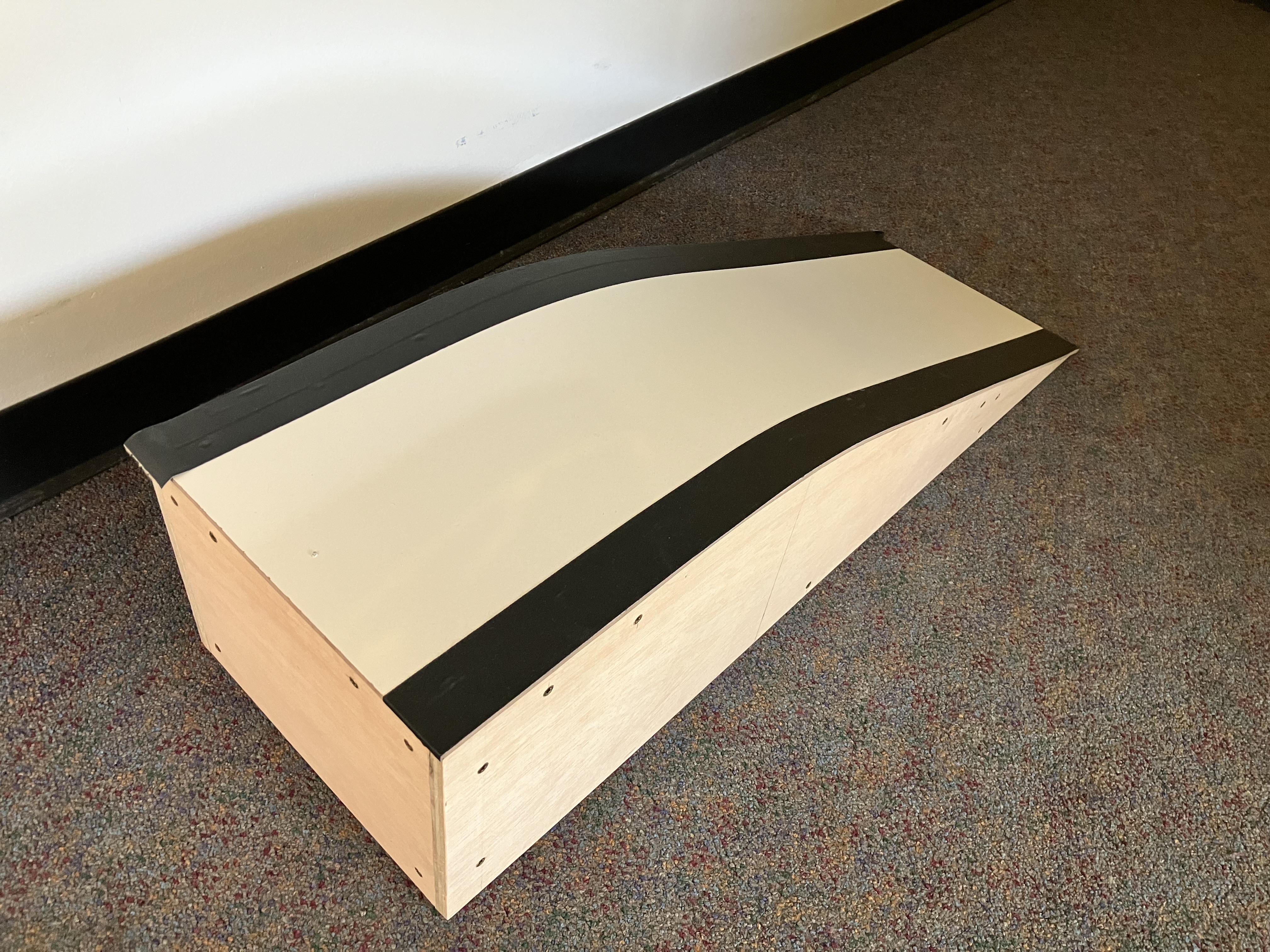
This is pretty fancy one, but the key elements that you need are easy to construct from reasonably stiff cardboard. The key properties it needs are:
- A sloped surface for the robot to climb with a roughly 15 degree slope.
- A flat surface on top for the robot to turn around.
- A light-colored surface.
- Dark colored edges that the robot can detect to not drive off the edge.
The ramp shown above is about 4 feet long and 1.5 feet wide.
8.1 Prelab
-
Read through the subsequent sections of this lab and state all of the requirements that your robot program must satisfy.
-
Review Section 6.5, Line and bump sensors of the Pololu 3pi+ 2040 robot User's Guide. How do the line sensors work? Is it possible to use the line sensors in combination with the bump sensors?
-
Recall from the Sensors lab that you used an accelerometer to measure pitch and roll of the robot. Assume you have a measurement p of pitch and r of roll. If the robot is sitting on a ramp and its x axis is pointing straight down the hill, then what values should you see for r? What should the sign of p be (assuming the angle is given in the range -π / 2 to π / 2)? You will use feedback control and adjust the wheel speeds to make r approach the desired value.
8.2 Line Sensing
For the hill-climbing exercise, your task is ultimately to get the robot to climb a ramp. So as to not damage the robot, you need to be sure that it will not drive off the edge of the ramp. Your first task, therefore, is to get the robot to take evasive action when it encounters the edge of the ramp.
Robots that navigate in the real world, such a Roomba vacuum cleaning robot, typically include "cliff sensors," which detect when the edge of the robot hangs over an empty space, for example at the top of a stairway. These are often implemented with ultrasonic distance sensors pointing down. The Pololu robot has infrared LEDs pointing down and sensors that detect infrared light. If the LEDs are the main source of infrared light, then these sensors can function as cliff sensors, but often ambient light includes infrared light. The sensors, therefore, more reliably detect the difference between a light-colored and dark-colored surface under the robot. A common exercise in robotics is to get a robot equipped with such sensors to follow a line made with dark-colored tape. Hence, these IR sensors are often called "line sensors."
Here, you will use the line sensors to detect the edges of the ramp, which, as shown in the image above, should be covered with a dark surface. Your task now is to program the robot to identify when its front end is above one of these edge markers and have it stop. If you have a higher risk tolerance, you could do without the dark bands and use the IR sensors to detect when the front of the robot is hanging over the edge of the ramp, but you will need to make sure there is little ambient IR light.
NOTE: According to Section 6.5, Line and bump sensors of the Pololu 3pi+ 2040 robot User's Guide, it is not practical to use the bump sensors in combination with the line sensors. Hence, in this lab, you will only use the line sensors.
First, you will get familiar with the line sensors. Then you will use them. Your tasks:
-
Examine and run the provided program
src/LineDisplay.lf. How does this work? Use it to calibrate your robot on the ramp so that it reliably detects when the front of the robot is over the dark bands on the edges (or, if you choose the riskier option, over the edge of the ramp). Note that calibration information is lost each time you upload a new program to the robot, so for reliable behavior, you will need to recalibrate each time you flash a new program onto the robot. -
Create a Lingua Franca program
HillLineDetectSolution.lfthat displays on the LCD display Left if either of the two left sensors detects a dark surface (or cliff), Right if either of the two right sensors detects a dark surface (or cliff), and Center if any of the three center sensors detects a dark surface (or cliff). Note that more than one of these might be displayed at the same time.Checkoff: Show that your program detects edges of the ramp. You can manually push the robot towards the edge to check.
-
Create a Lingua Franca program
HillLineAvoidSolution.lfthat drives the robot forward, but when the line sensors detect edges, backs up, turns, and then moves forward again. The direction in which the robot turns should be influenced by whether the edge is detected in front of the robot, to the left, or to the right.Checkoff: Show your robot navigating on the ramp and avoiding the edges.
8.3 Hill Climbing
Your final task is to add accelerometer and gyroscope measurements to your navigation code so that while the robot is on the slope of the ramp, it turns and drives towards the top. When it reaches the plateau at the top, it should turn 180 degrees and then drive down to the bottom of the ramp. All the while, it should avoid the edges of the ramp. Please put your solution in a file called HillClimbSolution.lf.
Hint: To drive up or down the ramp, periodically adjust the wheel speeds to attempt to keep the roll measurement near zero. That is, if the roll measurement is positive, adjust up the speed of one wheel and down the speed of the other. If the roll is negative, perform the opposite adjustment. If you make the adjustment proportional to the roll, then adjustments will get smaller as the robot more closely approximates heading straight up or down the ramp. You may want to review Section 2.4, Feedback Control, of Lee and Seshia. You will want to keep the wheel speeds within reasonable bounds.
Hint: The power needed by the motors to maintain a constant speed varies considerably as a function of the pitch.
A variant of the Motors reactor called MotorsWithFeedback is provided for you in the template repo in the src/lib directory.
The inputs to this reactor are desired speed and encoder readings.
Each time the reactor receives an encoder reading, it adjusts the power to the motors to attempt to get the measured speed to match the desired speed.
Hence, it can compensate (somewhat) for the pitch induced by the ramp.
Checkoff: Show your robot driving to the top, turning around, and going down the ramp.
Postlab
-
Encoders report the angle of the wheels in degrees relative to some starting point. Explain how the
MotorsWithFeedbackreactor uses this data to estimate the speed at which the robot is actually traveling. -
What were your takeaways from the lab? What did you learn during the lab? Did any results in the lab surprise you?
9 Track and Line Following
The goal of this exercise is to program the Pololu robot in LF to perform track and line following, where the robot detects a line or track and follows it until it reaches the end.
For this lab, you will need a suitable line like the ones below, made using black poster chart paper (cut in the shape of the track) or black ducktape on white foam boards:
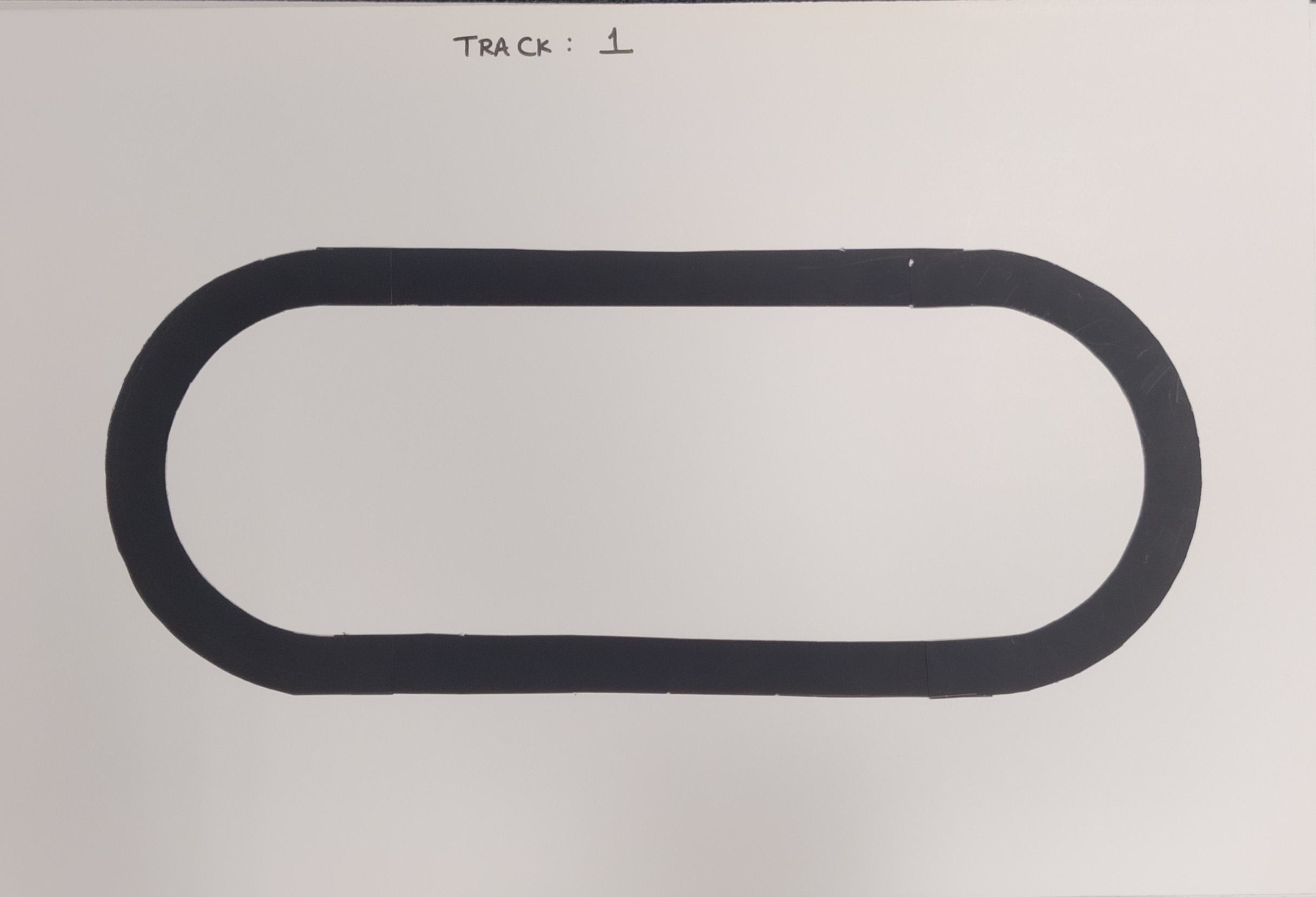 |
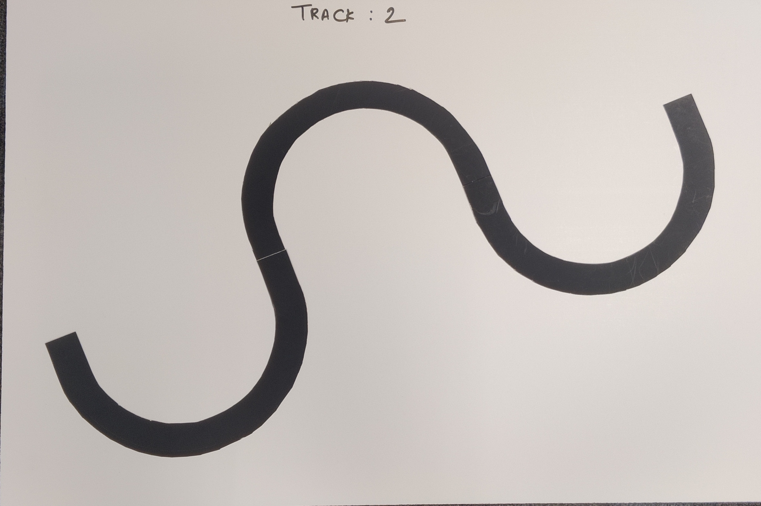 |
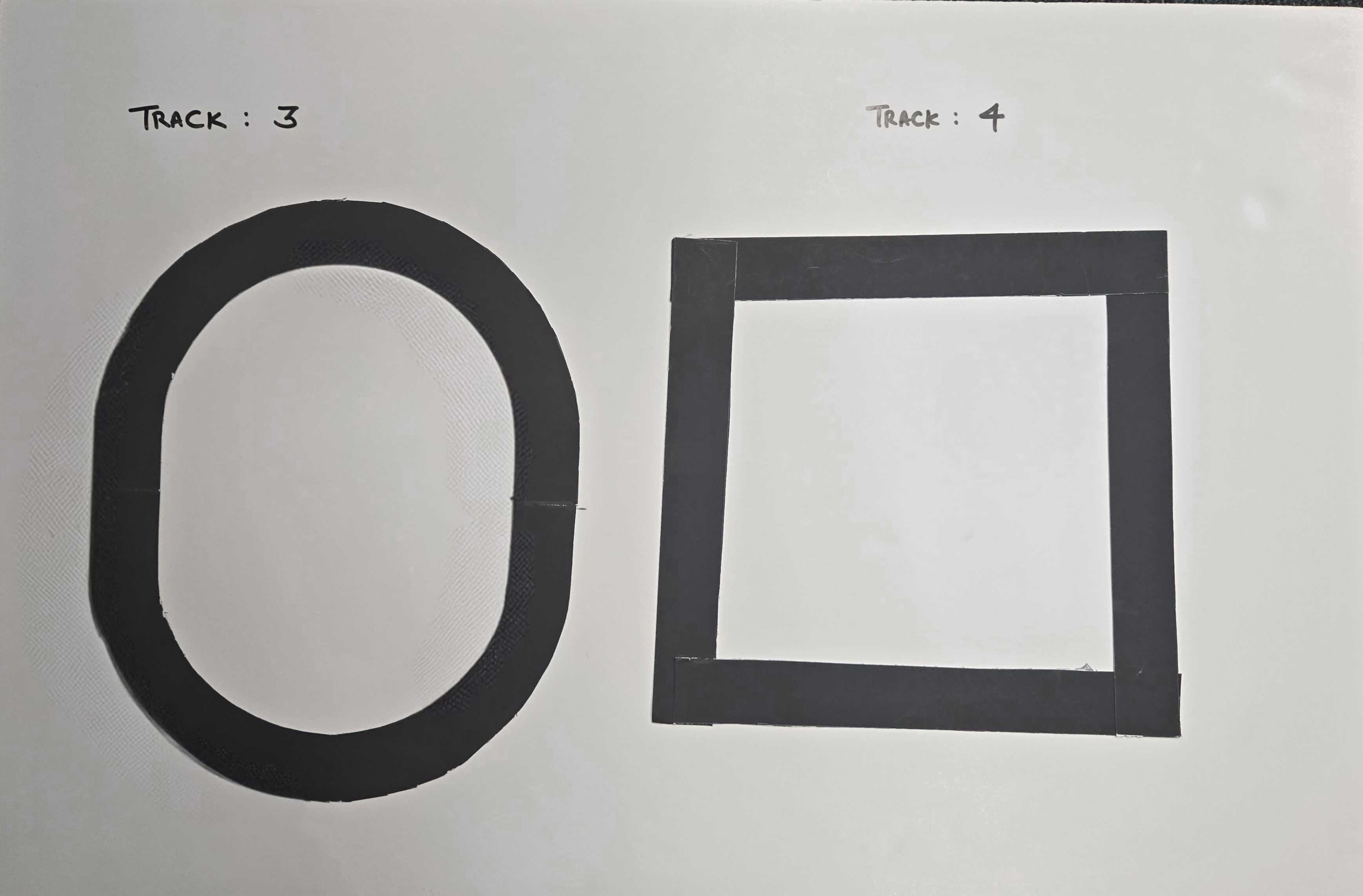 |
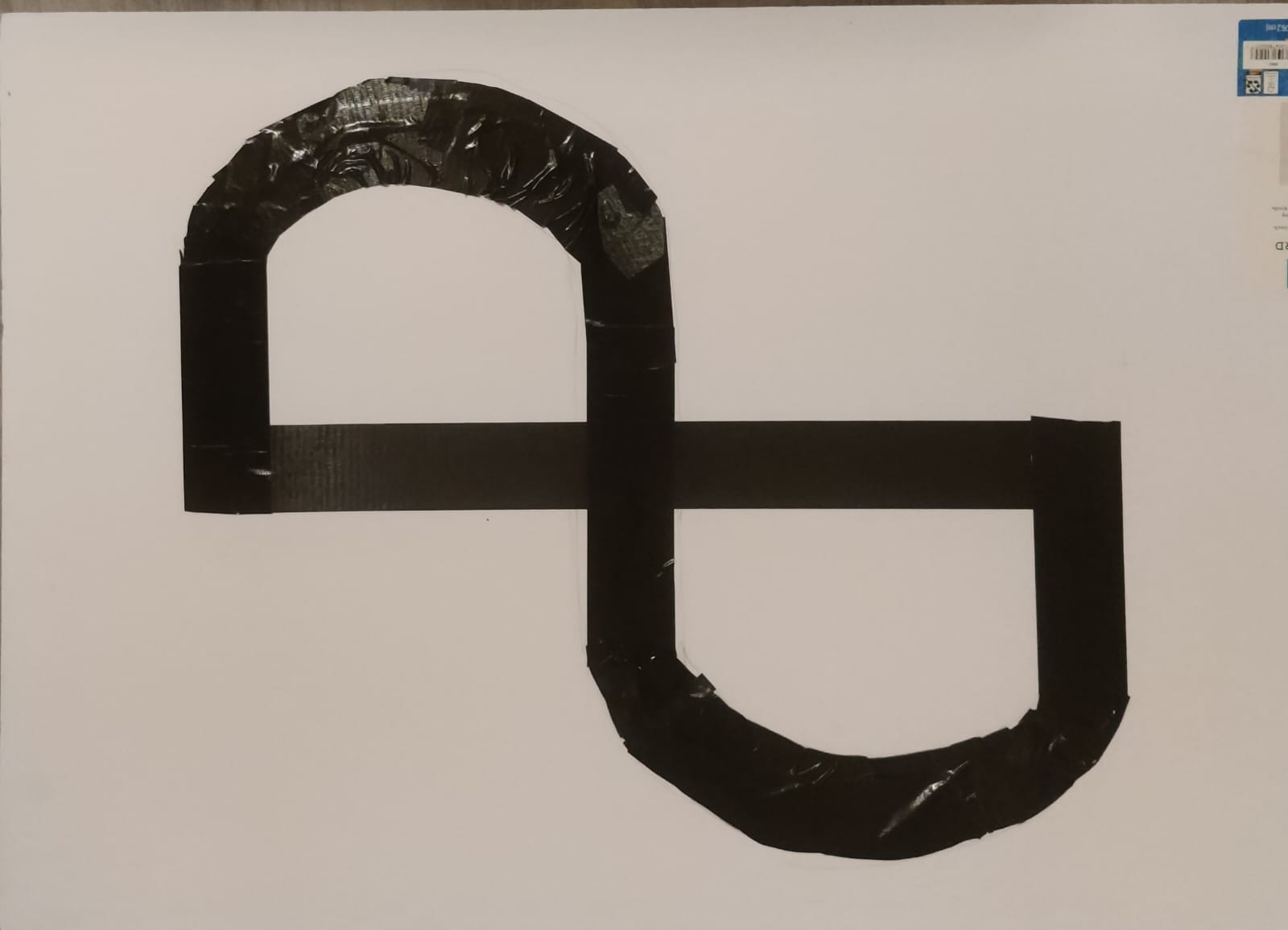
|
9.1 Prelab
-
Review Section 6.5, Line and bump sensors of the Pololu 3pi+ 2040 robot User's Guide.
-
Review the section for the motors from the previous lab. This lab will test you on how to adjust power to maneuver curves and sharp turns.
-
Review Line Sensing. The same calibration should be done at the beginning of this exercise, however, with a small difference, explained below.
For this lab, you are required to indicate where the robot is planning or programmed to move when the sensor detects an out-of-track area in order for the robot to realign itself with the track (For instance, if the right-hand-side sensors of the robot detect an out-of-track area the print on display should read "left" and vice-versa).
Questions
- Can we use the gyroscope to make the robot navigate the curves?
- Can we use the line sensors on the edges, i.e., sensors 1 and 5, to detect angles and curves?
9.2 Track Following
Checkoff: Calibrate your line sensors to detect the "out-of-track" area.
Write LF code to make your robot follow the designated path. The trick is to make sure the speed of the robot's motor enables it to maneuver the turns and adjust the speed of the robot if necessary.
HINT: 0.1f would be a reasonable starting point for the speed. You may increase or decrease the speed eventually. The goal is functionality.
You may build a track at your own home to test your code. The important thing to keep in mind is that the track must be smooth, and the robot should not get stuck somewhere in between. The key thing is that the track and the surroundings must have a significant contrast in terms of color. You are free to test your code on that track before you submit the code for it. The robot should align itself without any external help, even if it starts out skewed with respect to the track. The robot should stop at the end of the track or keep continuing if the track is a loop. You are free to include any module of your choice to make sure the robot is precise in keeping itself on track, and the robot should have enough intelligence or functionality to keep itself on track. The robot will be tested on a different track from the one you developed your code with to ensure uniformity. Please put your solution in a file called TrackFollowSolution.lf.
Checkoff: Show your robot driving to the end of the track and handling the curves smoothly.
9.3 Postlab
- What were your takeaways from the lab? What did you learn during the lab? Did any results in the lab surprise you?
- What method or logic did you use to tackle curves and sharp angles during the experiment?
- Justify or explain the logic behind choosing that particular method.
Documentation and Tutorials
Programming in C
Unix Command-line Tools
Pololu 3pi+ 2040 robot
RP2040 and RPi-Pico Programming
- Getting Started (pdf)
- Raspberry Pi Pico C/C++ SDK
- Pico SDK documentation
- SDK source code
- SDK examples
- Pico Extras
- RP2040 Datasheet (pdf)
Processor Reference
- ARM Cortex-M0+ datasheet
- ARM Cortex-M0+ Technical Reference Manual
- Armv6-M Architecture Reference Manual
General Raspberry Pi Documentation
Host computer tools
- Nix (for installation)
- Lingua Franca
- picotool (for downloading to the platform)
- screen terminal (for seeing standard out over USB)
Acronyms
| ADC | Analog to Digital Converter |
| AHB | Advanced High-performance Bus |
| APB | Advanced Peripheral Bus |
| CLI | Command-Line Interface |
| GPIO | General-Purpose Input/Output |
| I2C | Inter-Integrated Circuit, pronounced as “eye-squared-C” |
| IMU | Inertial Measurement Unit |
| I/O | Input / Output |
| ISR | Interrupt Service Routine |
| LF | Lingua Franca |
| LPF | Low Pass Filter |
| LSB | Least Significant Bit |
| NMI | Non-Maskable Interrupt |
| ODR | Output Data Rate |
| PWM | Pulse Width Modulation |
| RPi | Raspberry Pi |
| SDK | Software Development Kit |
| SIO | Single-cycle I/O |
| SPI | Serial Peripheral Interface |
| UART | Universal Asynchronous Receiver-Transmitter |
| USB | Universal Serial Bus |
| VS Code | Visual Studio Code |
Using a Debugger
Debugging
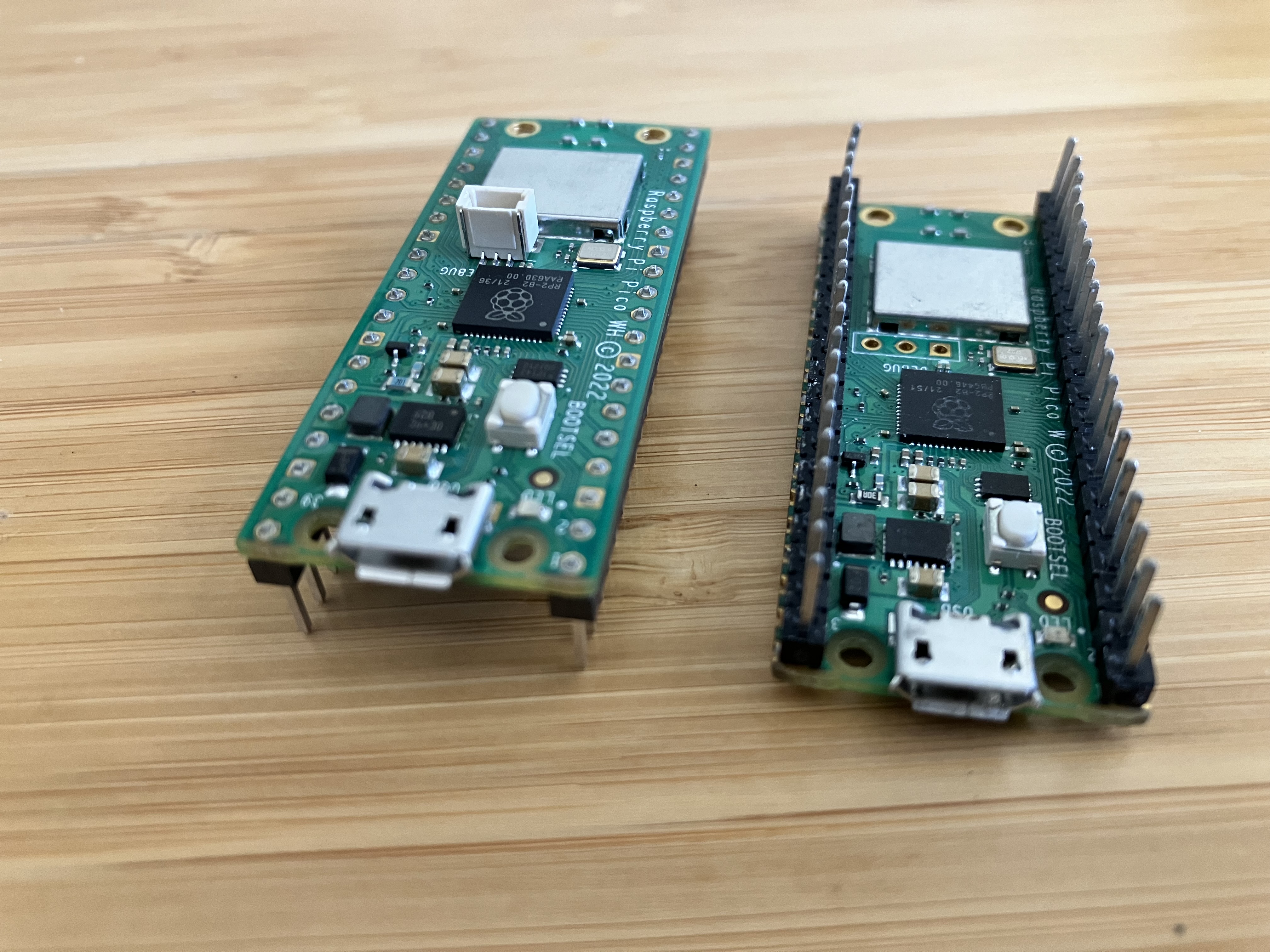
Interactive debugging, using for example gdb, is where you set breakpoints in your program, can step through the program line-by-line, and can examine variable values while the program is running. It allows far greater visibility than what you can achieve by just inserting print statements into your program. However, it is considerably more challenging to get interactive debugging working on an embedded device such as the RP2040 on the Pololu robot than on a program running on your host computer. Here, we explain how this can be accomplished, but it requires wiring a secondary embedded device, a Raspberry Pi Pico, to the Pololu robot and then connecting your host computer to the secondary Pico using its Micro USB interface.
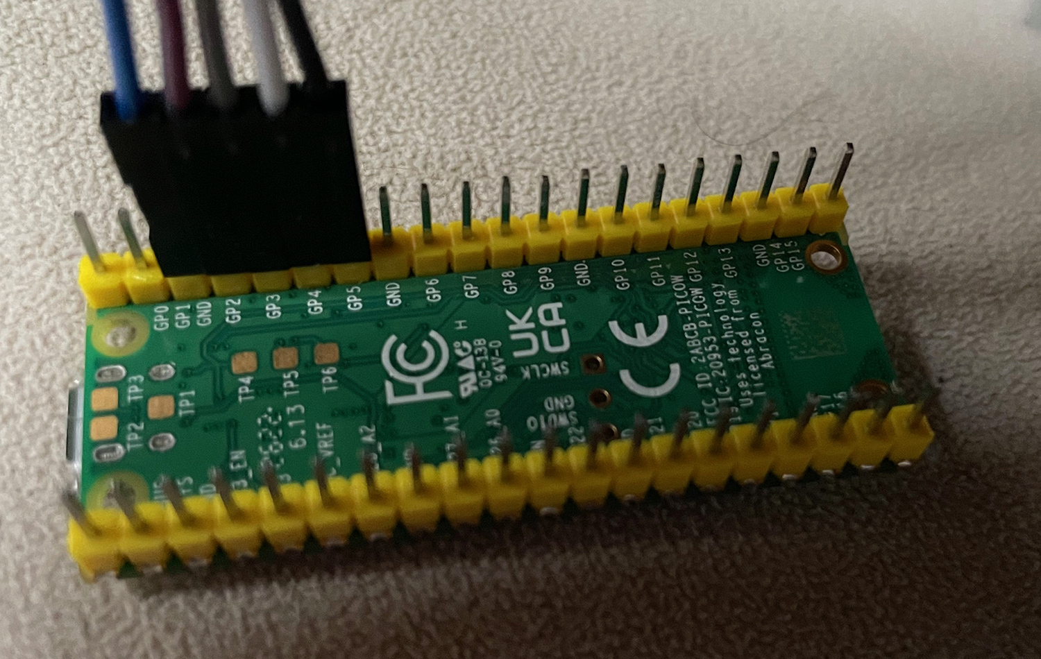
The secondary Pico looks like this:
Requirements
Detailed instructions can be found in Appendix A of the Getting Started with Raspberry Pi Pico document.
You will need the following hardware:
- A Raspberry Pi Pico
- A Micro USB cable
- Female to female jumper cables (5)
Software that you will need:
Your favorite package manager may work to install the on-chip debugger software, openocd, on your host computer. E.g., on a Mac,
$ brew install openocd
Detailed instructions for installing from source on various platforms can be found in Appendix A of the Getting Started with Raspberry Pi Pico document.
Picoprobe
The first step is connect the Pico to your computer using the Micro USB cable while holding the BOOTSEL button. The Pico should appear like an external disk on your computer. You can now install applications on it using picotool, just as you installed LF programs on the robot. NOTE: If the Pico does not appear as an external disk, it is possible that your Micro USB cable is of the wrong type. Sadly, it is common for Micro USB cables to only include the wires that supply power, not the wires needed for transferring data. The manufacturers probably saved a few micropennies.
The particular application you will need on the Pico is picoprobe. This application allows a Raspberry Pi Pico to act as a cmsis-dap device which interacts with the target RP2040 on the robot through a serial wire debug (SWD) interface connection. Dowload the picoprobe.elf file (or the picoprobe.uf2). Then, with your Pico in BOOTSEL mode, upload the file:
$ picotool load picoprobe.elf
Now, your Pico is ready to serve as a debugging bridge.
Wiring
Once the probe device (the Pico) is prepared, wire it up to the target device (the robot) as follows:
Probe GND -> Target GND
Probe GP2 -> Target SWCLK
Probe GP3 -> Target SWDIO
Probe GP4 (UART1 TX) -> Target GP1 (UART0 RX)
Probe GP5 (UART1 RX) -> Target GP0 (UART0 TX)
The last two wires connect the probe to UART0, which by default carries standard I/O and hence should make visible any printf outputs from your program through the probe.
You should be able to see this output using screen as explained in the Tools lab.
To make these connections, if you bought the robot assembled, then it likely came without expansion headers, so you will need to solder headers onto your robot so that it looks like this:
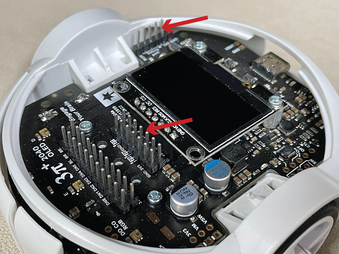
The particular pins on the robot headers that you need are labeled within the circles below:
With wires attached, it should look like this:
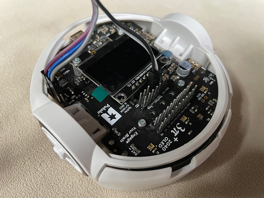
The wires needed on the Pico are these:
Complete wiring looks like this:
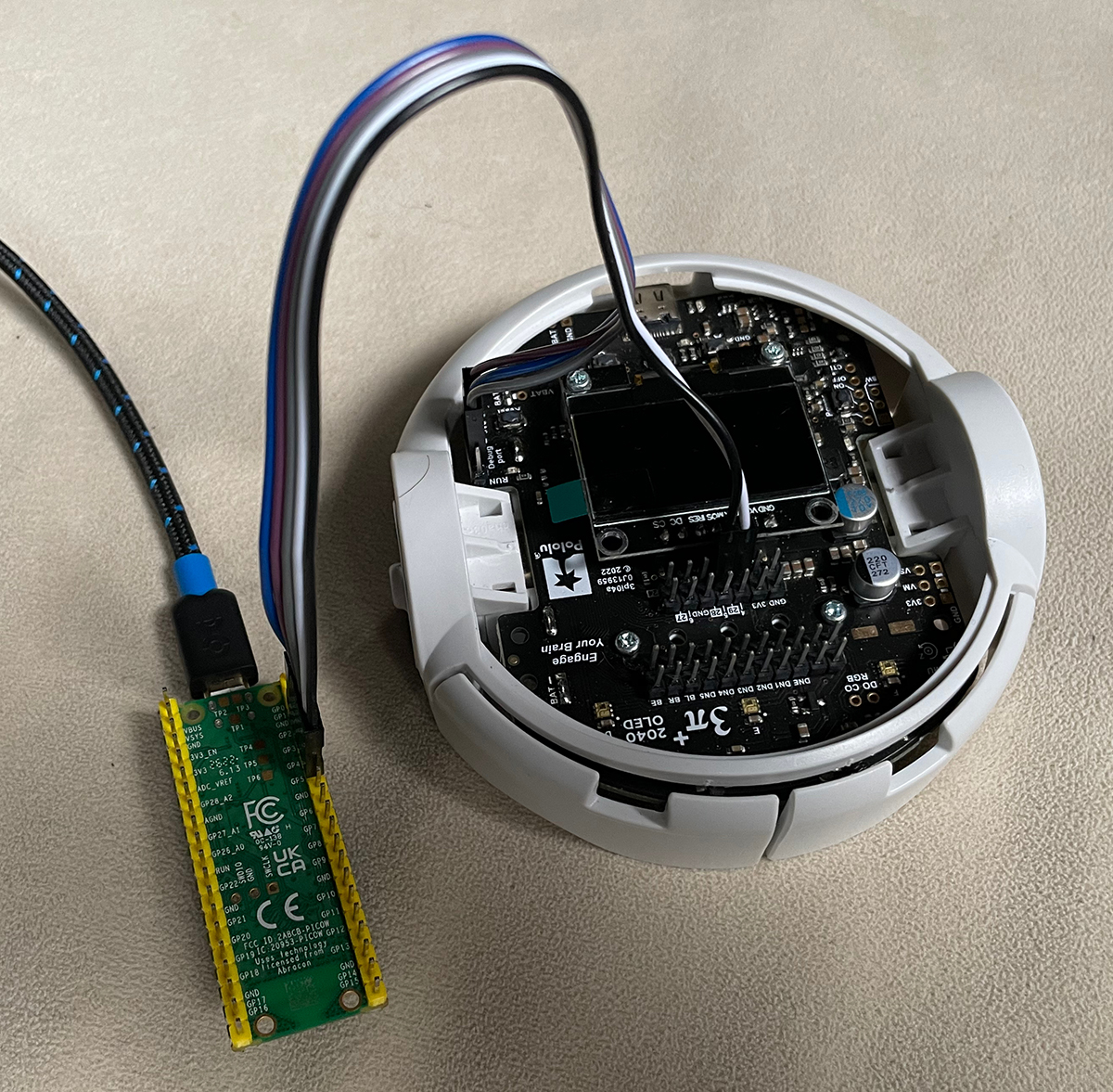
NOTE: The wiring connects the ground of the Pico to the ground of the robot, but there is no power connection to the robot. You will need to power the robot using its own batteries.
Debug Symbols
For a debugger to be able to meaningfully interact with an executing program, it is necessary for the binary .elf file that you flash onto the robot to include debug symbols.
This means that a symbol table is included in the binary that tells the debugger where in memory functions and variables are located.
For a Lingua Franca program to include such debug symbols, the target directive needs to include a build-type field set to debug, as follows:
target C {
  platform: {
    name: "rp2040",
    board: "pololu_3pi_2040_robot"
  },
  single-threaded: true,
  build-type: debug
}
To test this, modify src/Blink.lf to include the build-type field and compile the program:
lfc src/Blink.lf
This will create a file bin/Blink.elf that includes debug symbols.
OpenOCD
Open On-Chip Debugger is a program that runs on your host machine. It is a debug translator that understands the SWD protocol and is able to communicate with the probe device while exposing a local debug server for a debugger to attach to.
After wiring, run the following command to flash a Blink.elf binary with debug symbols onto the robot:
openocd -f interface/cmsis-dap.cfg -c "adapter speed 5000" -f target/rp2040.cfg \
    -c "program bin/Blink.elf verify reset exit"
The above will specify the
- probe type:
cmsis-dap - the target type:
rp2040 - commands: the
-cflag will directly run open ocd commands used to configure the flash operation.adapter speed 5000makes the transaction faster.program <binary>.elfspecifies theelfbinary to load into flash memory.verifyreads the flash and checks against the binary.resetresets and starts executing the program.exitdisconnects openocd.
When this is finished, the LED on the robot should be blinking.
GDB
The gnu debugger gdb is an open-source program for stepping through application code. Here we use the remote target feature to connect to the exposed debug server provided by openocd.
First restart openocd using the following command:
openocd -f interface/cmsis-dap.cfg -c "adapter speed 5000" -f target/rp2040.cfg -s tcl
Included in the output from the above command should be something like this:
Info : starting gdb server for rp2040.core0 on 3333
Info : Listening on port 3333 for gdb connections
Info : starting gdb server for rp2040.core1 on 3334
Info : Listening on port 3334 for gdb connections
In a separate terminal window, run the following gdb session specifying the .elf binary. Since this binary was built using the debug directive, it will include a symbol table that will be used for setting up breakpoints in gdb.
gdb bin/Blink.elf
Once the GDB environment is opened, connect to the debug server using the following. Each of the two cores exposes its own port.
With single-threaded set to true in the target directive, core0 runs the main thread, so you want to connect gdb to port 3333:
(gdb) target extended-remote localhost:3333
This will connect gdb to the executing program and stop the program at whatever point it happens to be running. You will see output something like this:
Remote debugging using localhost:3333
alarm_pool_get_default () at /Users/eal/git/lf-3pi-template/pico-sdk/src/common/pico_time/time.c:93
93	alarm_pool_t *alarm_pool_get_default() {
This means that the program halted at line 93 of a Pico SDK file called time.c.
The LED should no longer be blinking.
From this point on, normal gdb functionality such as breakpoints, stack traces, and register analysis can be accessed through various gdb commands. A gdb tutorial might be helpful at this point.
To set a breakpoint at a Lingua Franca reaction, and relatively easy way to to that is to find the function name for the function generated by lfc for the reaction.
For the Blink program, you can examine the generated code using VS Code:
code src-gen/Blink/
In the file _blink_main.c, there are two functions, _blink_mainreaction_function_0 and _blink_mainreaction_function_1.
These correspond to the two reactions in Blink.lf, where the main reactor is this:
main reactor {
  timer t(0, 250 ms);
  state led_on:bool = false;

  reaction(startup) {=
    gpio_init(PICO_DEFAULT_LED_PIN);
    gpio_set_dir(PICO_DEFAULT_LED_PIN, GPIO_OUT);
  =}
  reaction(t) {=
    self->led_on = !self->led_on;
    gpio_put(PICO_DEFAULT_LED_PIN, !self->led_on);
  =}
}
In gdb, you can set a breakpoint at the second of these reactions, examine the stack, print variable values, etc. For example, here is an interactive session:
(gdb) break _blink_mainreaction_function_1
Breakpoint 1 at 0x10000304: file /Users/eal/git/lf-3pi-template/src/Blink.lf, line 26.
Note: automatically using hardware breakpoints for read-only addresses.
(gdb) continue
Continuing.

Breakpoint 1, _blink_mainreaction_function_1 (instance_args=0x200028f8) at /Users/eal/git/lf-3pi-template/src/Blink.lf:26
26	    self->led_on = !self->led_on;
(gdb) print self
$1 = (_blink_main_main_self_t *) 0x200028f8
(gdb) print self->led_on
$2 = false
(gdb) next
27	    gpio_put(PICO_DEFAULT_LED_PIN, !self->led_on);
(gdb) print self->led_on
$3 = true
(gdb) next
_lf_invoke_reaction (env=env@entry=0x200018d0 <envs>, reaction=reaction@entry=0x20002970, worker=worker@entry=0)
    at /Users/eal/git/lf-3pi-template/src-gen/Blink/core/reactor_common.c:1351
1351	    ((self_base_t*) reaction->self)->executing_reaction = NULL;
(gdb)
At this point, the LED should have gone from off to on (or on to off, depending on its state when you connected gdb).
Visual Studio Code
Breakpoints can be placed in generated lingua franca project source code within vscode.
As a part of the code generation process, each lfc generates a .vscode directory in the program src-gen folder.
This is populated with settings to configure and run gdb, openocd and cmake.
Run the following after generating code for the desired lf program:
$ code src-gen/Blink/
In vscode, navigate to the run and debug tab on the left. A Pico Debug option should appear at the top as shown here:
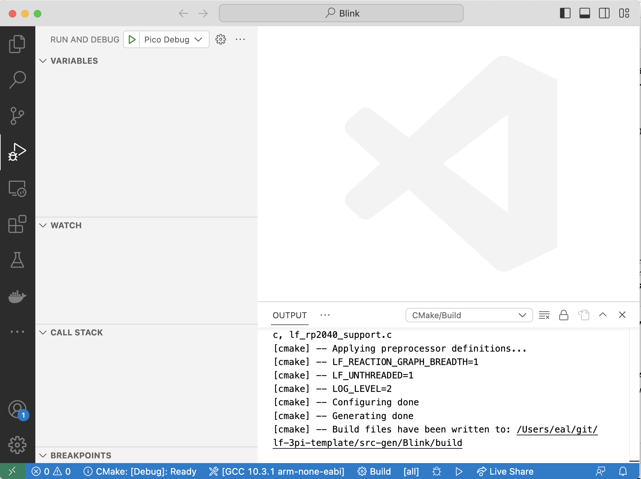
First, you will need for VS Code to build the project. Clean up from the previous lfc builds as follows:
rm -rf src-gen/Blink/build
Then click on the blue Build button at the bottom of the VS Code window.
Make sure the picoprobe is connected and wired as noted above and click run (the green triangle). The debugger should automatically break
at the main method of the application. Breakpoints can be visually inserted and other debugger options are accessible through
the IDE gui.
Troubleshooting: Depending on the platform you are running on and how gdb was installed, you may see the following error when try to run the program:
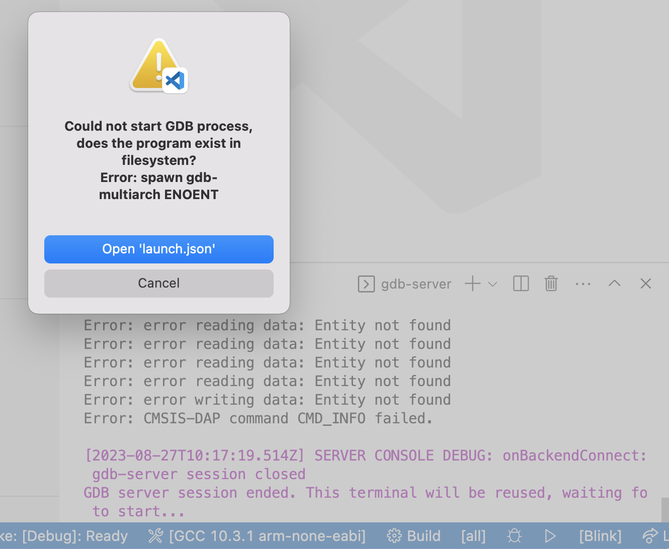
Click on Open 'launch.json' and edit this line:
"gdbPath" : "gdb-multiarch",
This line specifies the gdb program to use. It may be simply:
"gdbPath" : "gdb",
Non-nix Setup
If you use nix as explained in the getting started instructions, then you should not need to manually install the Raspberry Pi Pico SDK, C library and math library compiled for bare metal Cortex ARM, or the GNU Arm Embedded Toolchain for cross-compilation. To install these manually and not rely on nix to provide these dependencies, follow these instructions.
Install Raspberry Pi Pico SDK
Clone the raspberrypi/pico-sdk repository (and its submodules) and set the PICO_SDK_PATH environment variable:
$ git clone https://github.com/raspberrypi/pico-sdk.git
$ cd pico-sdk
$ git submodule update --init
$ export PICO_SDK_PATH=`pwd`
For convenience, set PICO_SDK_PATH in your ~/.profile file so that the environment variable is available to any bash terminal. After completing the steps above, this can be done as follows:
$ echo "export PICO_SDK_PATH=$PICO_SDK_PATH" >> ~/.profile
Caution: Depending on what operating system and terminal you use, and how it is configured, you may need to find some other way to set this environment variable.
Install picotool
To build and install picotool from source, run the following commands:
$ git clone https://github.com/raspberrypi/picotool.git
$ cd picotool
$ mkdir build
$ cd build
$ cmake ..
$ make
$ sudo make install
Install CMake, Standard C Library, ARM cross compiler
For reference, see the GNU ARM installation instructions. For installation instructions specific to Ubuntu and macOS, read on.
On Ubuntu
sudo apt update
sudo apt install cmake make gcc gcc-arm-none-eabi libnewlib-arm-none-eabi
On macOS
$ brew install cmake make gcc arm-none-eabi-gcc
$ brew tap ArmMbed/homebrew-formulae
NOTE: If you are running on an Apple M1-based Mac you will need to install Rosetta 2 as the Arm compiler is still only compiled for x86 processors and does not have an Arm native version.
$ /usr/sbin/softwareupdate --install-rosetta --agree-to-license
Perform a Smoke Test
To make sure your installation has worked, follow the instructions here.
Project Ideas
There are many possible projects using the Pololu 3pi+ 2040 robot. Several of these will require access to the expansion ports (see Tools and Environments).
-
Low power robot. The ARMv6 processor in the RP2040 has a specialized instruction for putting the processor to sleep until an interrupt occurs. The goal of this project is to use this instruction to reduce the energy consumption of Lingua Franca programs running on the processor. A significant part of the project is to design the experiments that measure energy use and to determine when the sleep instruction should be used and when it should not be used. A demonstration should include an LF application that lie quiescent for an indefinite period of time while nothing is happening and yet remain reactive to external events, e.g., shake the robot to wake it up. The accelerometer on the Pololu robot has a low power event detection mode that could be used for this purpose.
-
Interactive debugging. The RP2040 processor has a debugging interface that can be connected to a secondary Raspberry Pi Pico running a monitoring program called FIXME. The secondary RP Pico can in turn be connected to a host computer running gdb, lldb, or the debugger in VS Code to achieve interactive debugging. The goal of this project is to develop the hardware, software, and engineering processes for conveniently performing interactive debugging of Lingua Franca programs running on the Pololu robot. This includes designing and manufacturing a printed circuit board that bridges a header on the robot with the secondary RP Pico. It also includes investigating the VS Code debugging API to determine whether it is possible to debug directly from the LF source code (vs. the generated C code, which certainly should be possible).
-
Bare metal multithreading. The RP2040 has two cores, only one of which is used by Lingua Franca when the threading target parameter is set to false. It should be possible to enable multi threading and limit the number of threads to two, one running on each core. This project will redesign the LF platform support to accomplish this. This will require learning how the two cores interact through memory and peripherals as well as how LF uses multi threading. The project should include designing experiments to measure the efficiency of the approach and the benefits compared to the unthreaded implementation that uses only a single core.
-
Hard-real-time I/O. The RP2040 processor on the Pololu robot has innovative programmable I/O (PIO) peripherals, which are GPIO pins connected to a simple programmable state machine that can deliver extremely precise timing for voltage changes on the pins. The goal of this project to assess the performance of such peripherals, to build Lingua Franca components that can use them, and to develop an application that needs the timing precision. A good application might be a "persistence of vision" display, where a moving LED strip is able to display an image by precisely controlling the timing at which the LEDs are turned on and off (see, for example, this demo).
-
Bluetooth connected robot. The Pololu robot has no network connectivity, but it has two UARTs, one of which could be dedicated to providing a serial connection over bluetooth. The goal of this project is to identify a serial bluetooth device that can be connected to the one of the UARTs and then to develop demonstrations of robot control over bluetooth.
-
Runtime monitoring. Given a temporal logic formula that refers to modes of an LF modal model and values of state variables, it should be possible to create a runtime monitor that checks whether the execution of the program satisfies the formula. Use this strategy to create an "auto grader" for the robot labs that you just completed.
-
Simulator integration. Often, prototyping software on real robots is too dangerous or expensive. In this project, you will use the Webots simulator to create a 3-D model of the Pololu robot and run the Lingua Franca code with the simulator rather than a real robot. This will require implementing the sensor and actuator reactors to interact with the simulator rather than with the robot.
-
AI robot. According to its wikipedia page, the RP2040 is sufficiently powerful to run TensorFlow Lite. The goal of this project is to test this claim and develop some meaningful application running on the robot and using machine learning.
-
Distributed computing using Zephyr. Lingua Franca supports distributed computing on platforms such as Linux and macOS. Recent work has also been done to support distributed LF programs on Zephyr. There is Zephyr support for both the RP2040 and for running BSD Sockets over the USB connection of the RP2040. The goal of this project is to run a distributed LF program spanning a RP2040 and a Linux desktop through a USB connection. Support for distributed LF on Zephyr is provided in this PR.
-
Symmetric multi-processing using FreeRTOS. FreeRTOS is a free and popular real-time operating system with support for symmetric multiprocessing (SMP) on RP2040. This project consists of getting the SMP sample applications from FreeRTOS running on the RPi Pico and eventually adding LF platform support for FreeRTOS. The project should include some experiments to evaluate the performance of the approach. More info on SMP using Pico and FreeRTOS here.
Notes for VM users
Accessing USB Devices
If you are using the pre-configured VM image, you need to ensure that it can access the RP2040 on the USB port of the host computer. For more information about configuring VirtualBox to allow this, see this article.
Installing the Extension Pack
To enable USB-2 support (and various other features), an additional extension pack must be installed on the host machine.
- Installation instructions for Arch Linux
- Installation instructions for Ubuntu 22.04
- Installation instructions for Mac and Windows
Notes for Windows Users
WSL Setup
It is recommend to use the Windows Subsystem for Linux (WSL) when developing on a Windows machine. Use the following installation instructions to install USB support.
To mount the a Pico device to the WSL instance, run the following in an administrator powershell to find the correct bus and attach:
usbipd list
usbipd bind --busid <busid>
usbipd attach --wsl --busid <busid>
In the WSL instance, run the following to verify the device has mounted:
lsusb
Troubleshooting: udev in WSL
Due to USB being unofficially supported for WSL, the udev service daemon might need to be restarted after attaching usb devices to the WSL instance as outlined above. This has particularly been an issue when debugging with openocd. Run the following commands to restart the udev daemon and reapply udev rules.
$ sudo service udev restart
$ sudo udevadm trigger
Notes for Instructors
If you are teaching an embedded systems course and would like to use this material, please feel welcome to do so. This page provides resources for preparing a lab based on the software and hardware used in this lab manual.
Lingua Franca
These labs rely heavily on the use of Lingua Franca (LF), an open-source coordination language for designing and building systems that feature concurrency, may be reactive and/or time-sensitive, and may be distributed. It integrates seamlessly with existing target languages, including C, C++, Python, Rust, and TypeScript, and the C target is particularly suited for programming embedded systems. LF provides a component-based design methodology that allows programmers to take full advantage of existing manufacturer-supplied SDKs and legacy software while it equips programmers with powerful abstractions for specifying concurrent and timed system behavior.
Writing concurrent software that behaves deterministically and in accordance with timing requirements is a difficult an error-prone task when done using low-level primitives like threads, interrupts, and hardware timers. Lingua Franca provides syntax for defining and composing concurrent components called reactors, which react to events deterministically, supported by a dynamic runtime scheduling engine. While reactions to events can perform low-level interactions with the hardware (for example, to access a sensor or drive an actuator), this logic is entirely independent from the orchestration of interactions with other software components, which is taken care of automatically by the Lingua Franca runtime system. This approach facilitates building complex systems out of simple components and provides a more disciplined approach to system design.
The Pololu 3Pi+ 2040 Robots
The Pololu robot used in these labs is available for purchase here. The 3pi+ 2040 is a versatile, high-performance, user-programmable robot that measures just 9.7 cm (3.8") in diameter. At its heart is a Raspberry Pi RP2040 microcontroller (like the one on the Raspberry Pi Pico), a 32-bit dual-core Arm Cortex-M0+ processor running at 125 MHz.
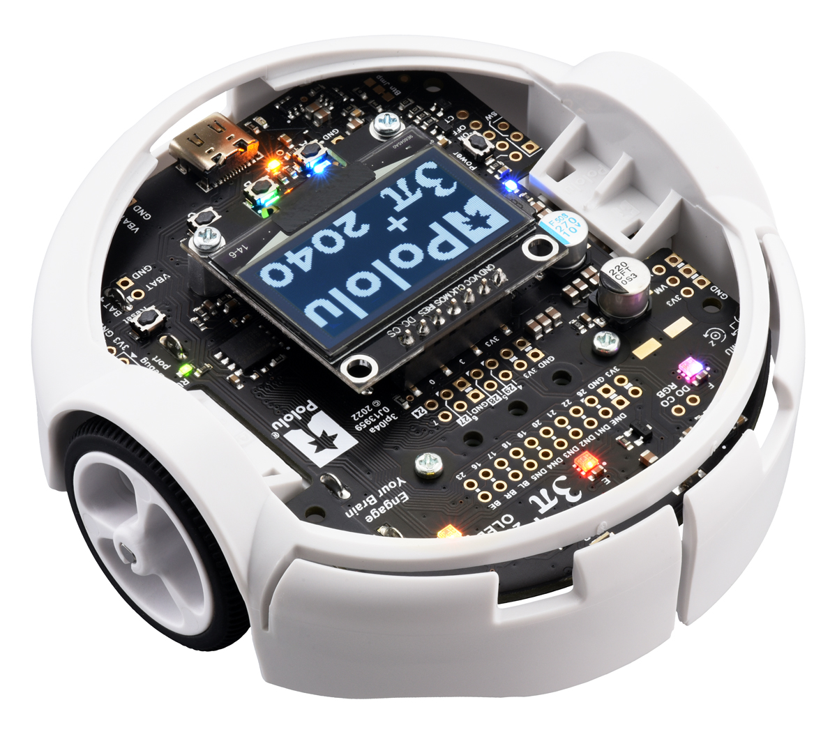
The robot is available as a kit or pre-assembled, and comes in different motor configurations:
- 30:1 MP 6V Micro Metal Gearmotors (Standard Edition, used in this lab)
- up to 1.5 m/s; offer a good combination of speed and controllability
- 75:1 LP 6V Micro Metal Gearmotors (Turtle Edition)
- up to 0.4 m/s; allow for longer battery life
- 15:1 HPCB 6V Micro Metal Gearmotors (Hyper Edition)
- up to 4 m/s; difficult to control, easy to damage
For more information, refer to the docs provided by Pololu.
The Ramp used for the Hill Climb
Build instructions for a ramp to use with the Hill Climb exercise will be posted here soon. The robots are very light-weight, however, so even a very flimsy ramp constructed using cardboard will probably do.
Solutions
We can provide access to solutions of the lab exercises upon request. Please contact eal at berkeley.edu to place an inquiry.
Institutions Using the Labs
The embedded systems labs with Lingua Franca have been used by various courses at institutions around the world, including the following (listed alphabetically):
- Arizona State University, United States — CSE 522: Real-Time Embedded Systems
- Southern Illinois University, United States — ECE 424/514: Design of Embedded Systems
- University of California, Berkeley, United States — EECS 149/249A: Introduction to Embedded and Cyber Physical Systems
- University of Manouba, Tunisia — ESDV.5.4: Cyber-Physical Systems, ESEP.5.3: Cyber-Physical Systems
- University of Maryland, United States — ENEB452: Advanced Software for Connected Embedded Systems
- University of Michigan-Dearborn, United States — ME 472: Principles and Applications of Mechatronic Systems, ECE 566 / ME 565: Mechatronics
If your institution is using the embedded systems labs but is not listed here, please email Hokeun Kim (hokeun@asu.edu) with your course information, or submit a pull request to add your course information.