8 Hill Climb
The purpose of this exercise is to program the Pololu robot to execute a specified task, namely to climb a ramp, detect when it reaches the top, turn around, and drive back down the ramp, all without falling off the edge of the ramp.
For this lab, you will need a suitable ramp like the one here:
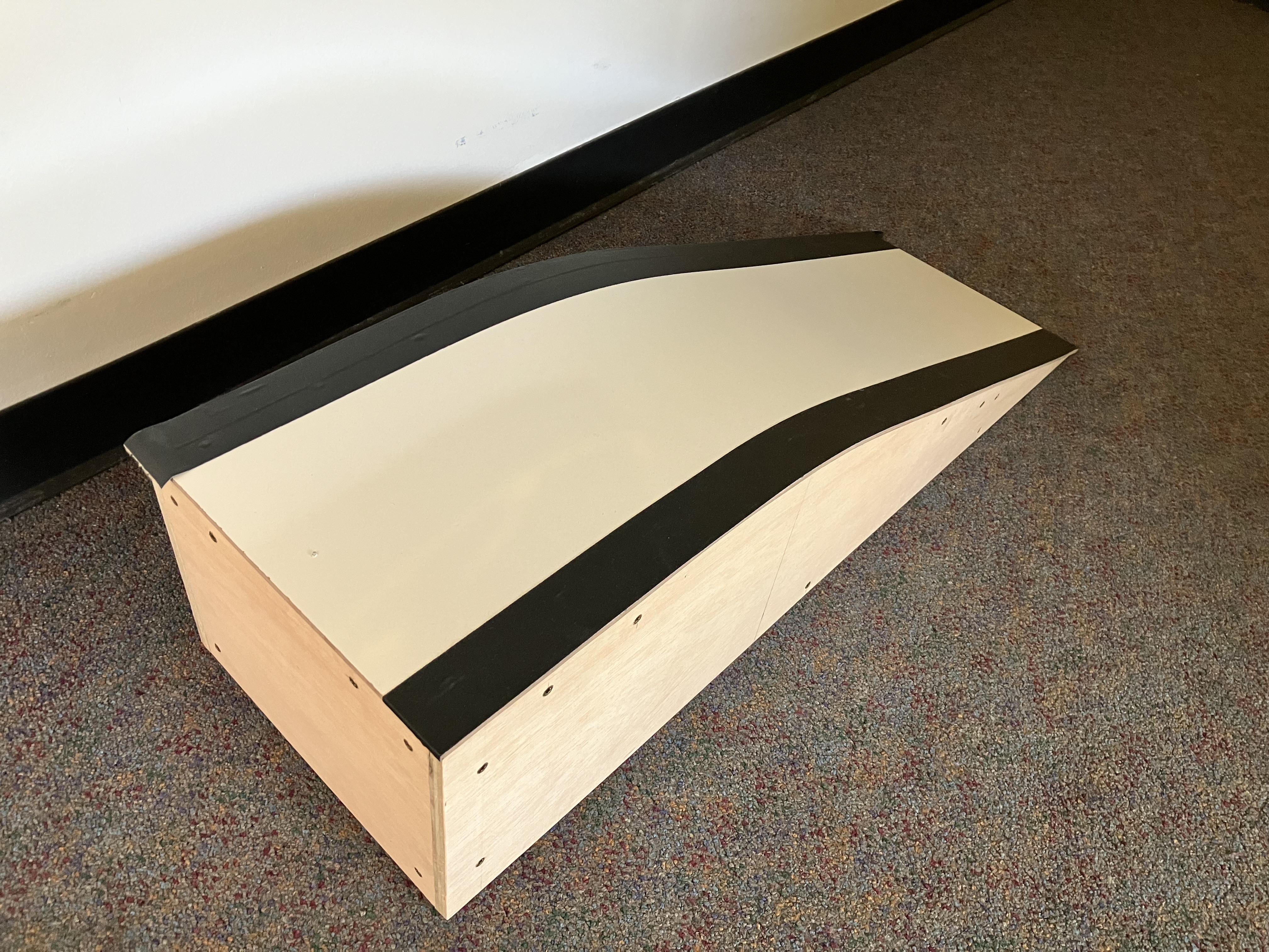
This is pretty fancy one, but the key elements that you need are easy to construct from reasonably stiff cardboard. The key properties it needs are:
- A sloped surface for the robot to climb with a roughly 15 degree slope.
- A flat surface on top for the robot to turn around.
- A light-colored surface.
- Dark colored edges that the robot can detect to not drive off the edge.
The ramp shown above is about 4 feet long and 1.5 feet wide.
8.1 Prelab
-
Read through the subsequent sections of this lab and state all of the requirements that your robot program must satisfy.
-
Review Section 6.5, Line and bump sensors of the Pololu 3pi+ 2040 robot User's Guide. How do the line sensors work? Is it possible to use the line sensors in combination with the bump sensors?
-
Recall from the Sensors lab that you used an accelerometer to measure pitch and roll of the robot. Assume you have a measurement p of pitch and r of roll. If the robot is sitting on a ramp and its x axis is pointing straight down the hill, then what values should you see for r? What should the sign of p be (assuming the angle is given in the range -π / 2 to π / 2)? You will use feedback control and adjust the wheel speeds to make r approach the desired value.
8.2 Line Sensing
For the hill-climbing exercise, your task is ultimately to get the robot to climb a ramp. So as to not damage the robot, you need to be sure that it will not drive off the edge of the ramp. Your first task, therefore, is to get the robot to take evasive action when it encounters the edge of the ramp.
Robots that navigate in the real world, such a Roomba vacuum cleaning robot, typically include "cliff sensors," which detect when the edge of the robot hangs over an empty space, for example at the top of a stairway. These are often implemented with ultrasonic distance sensors pointing down. The Pololu robot has infrared LEDs pointing down and sensors that detect infrared light. If the LEDs are the main source of infrared light, then these sensors can function as cliff sensors, but often ambient light includes infrared light. The sensors, therefore, more reliably detect the difference between a light-colored and dark-colored surface under the robot. A common exercise in robotics is to get a robot equipped with such sensors to follow a line made with dark-colored tape. Hence, these IR sensors are often called "line sensors."
Here, you will use the line sensors to detect the edges of the ramp, which, as shown in the image above, should be covered with a dark surface. Your task now is to program the robot to identify when its front end is above one of these edge markers and have it stop. If you have a higher risk tolerance, you could do without the dark bands and use the IR sensors to detect when the front of the robot is hanging over the edge of the ramp, but you will need to make sure there is little ambient IR light.
NOTE: According to Section 6.5, Line and bump sensors of the Pololu 3pi+ 2040 robot User's Guide, it is not practical to use the bump sensors in combination with the line sensors. Hence, in this lab, you will only use the line sensors.
First, you will get familiar with the line sensors. Then you will use them. Your tasks:
-
Examine and run the provided program
src/LineDisplay.lf. How does this work? Use it to calibrate your robot on the ramp so that it reliably detects when the front of the robot is over the dark bands on the edges (or, if you choose the riskier option, over the edge of the ramp). Note that calibration information is lost each time you upload a new program to the robot, so for reliable behavior, you will need to recalibrate each time you flash a new program onto the robot. -
Create a Lingua Franca program
HillLineDetectSolution.lfthat displays on the LCD display Left if either of the two left sensors detects a dark surface (or cliff), Right if either of the two right sensors detects a dark surface (or cliff), and Center if any of the three center sensors detects a dark surface (or cliff). Note that more than one of these might be displayed at the same time.Checkoff: Show that your program detects edges of the ramp. You can manually push the robot towards the edge to check.
-
Create a Lingua Franca program
HillLineAvoidSolution.lfthat drives the robot forward, but when the line sensors detect edges, backs up, turns, and then moves forward again. The direction in which the robot turns should be influenced by whether the edge is detected in front of the robot, to the left, or to the right.Checkoff: Show your robot navigating on the ramp and avoiding the edges.
8.3 Hill Climbing
Your final task is to add accelerometer and gyroscope measurements to your navigation code so that while the robot is on the slope of the ramp, it turns and drives towards the top. When it reaches the plateau at the top, it should turn 180 degrees and then drive down to the bottom of the ramp. All the while, it should avoid the edges of the ramp. Please put your solution in a file called HillClimbSolution.lf.
Hint: To drive up or down the ramp, periodically adjust the wheel speeds to attempt to keep the roll measurement near zero. That is, if the roll measurement is positive, adjust up the speed of one wheel and down the speed of the other. If the roll is negative, perform the opposite adjustment. If you make the adjustment proportional to the roll, then adjustments will get smaller as the robot more closely approximates heading straight up or down the ramp. You may want to review Section 2.4, Feedback Control, of Lee and Seshia. You will want to keep the wheel speeds within reasonable bounds.
Hint: The power needed by the motors to maintain a constant speed varies considerably as a function of the pitch.
A variant of the Motors reactor called MotorsWithFeedback is provided for you in the template repo in the src/lib directory.
The inputs to this reactor are desired speed and encoder readings.
Each time the reactor receives an encoder reading, it adjusts the power to the motors to attempt to get the measured speed to match the desired speed.
Hence, it can compensate (somewhat) for the pitch induced by the ramp.
Checkoff: Show your robot driving to the top, turning around, and going down the ramp.
Postlab
-
Encoders report the angle of the wheels in degrees relative to some starting point. Explain how the
MotorsWithFeedbackreactor uses this data to estimate the speed at which the robot is actually traveling. -
What were your takeaways from the lab? What did you learn during the lab? Did any results in the lab surprise you?