3. Tools and Environments
The purpose of this lab exercise is to familiarize you with the hardware and software used for embedded software programming. This lab exercise assumes you have followed the installation instructions. The Documentation and Acronyms pages will also prove particularly useful.
Embedded systems often have limited resources and interaction methods and hence require a different approach for programming. Their microprocessors often have no operating system, and are therefore called "bare metal" or "bare iron" machines. They often have no keyboard or display connected to them, which can make debugging your programs challenging. And they often have limited networking capability. These lab exercises will help you develop the capability to build sophisticated programs for such embedded systems.
In this lab exercise, you will learn to interact with a particular microcontroller, a Raspberry Pi RP2040 on the Pololu 3pi+ 2040 robot. The RP2040 microcontroller is a low cost dual-core chip designed by the Raspberry Pi Foundation in association with Broadcom. Each core implements the ARM Cortex-M0+ instruction set and is clocked at 133 MHz. The same RP2040 microprocessor is also available on the low-cost Raspberry Pi Pico board, but this board does not have the sensors and actuators of the Pololu robot, so you will need the robot to be able to complete all the exercises. See the Raspberry Pi Wikipedia page for more background on this family of microcontrollers.
Hardware
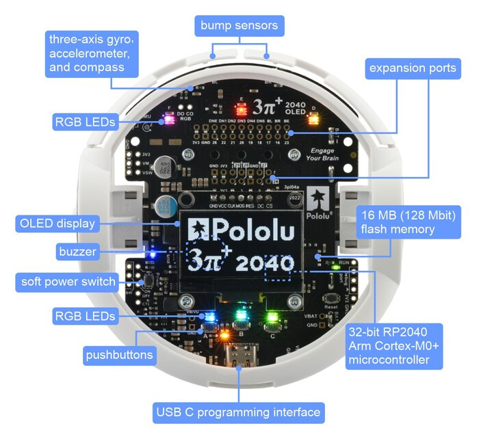
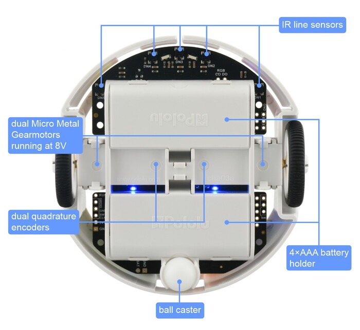
The Pololu 3pi+ 2040 robot looks like this from the top and bottom:
The robot is designed to be extended with additional hardware. The available electrical interfaces are shown below:
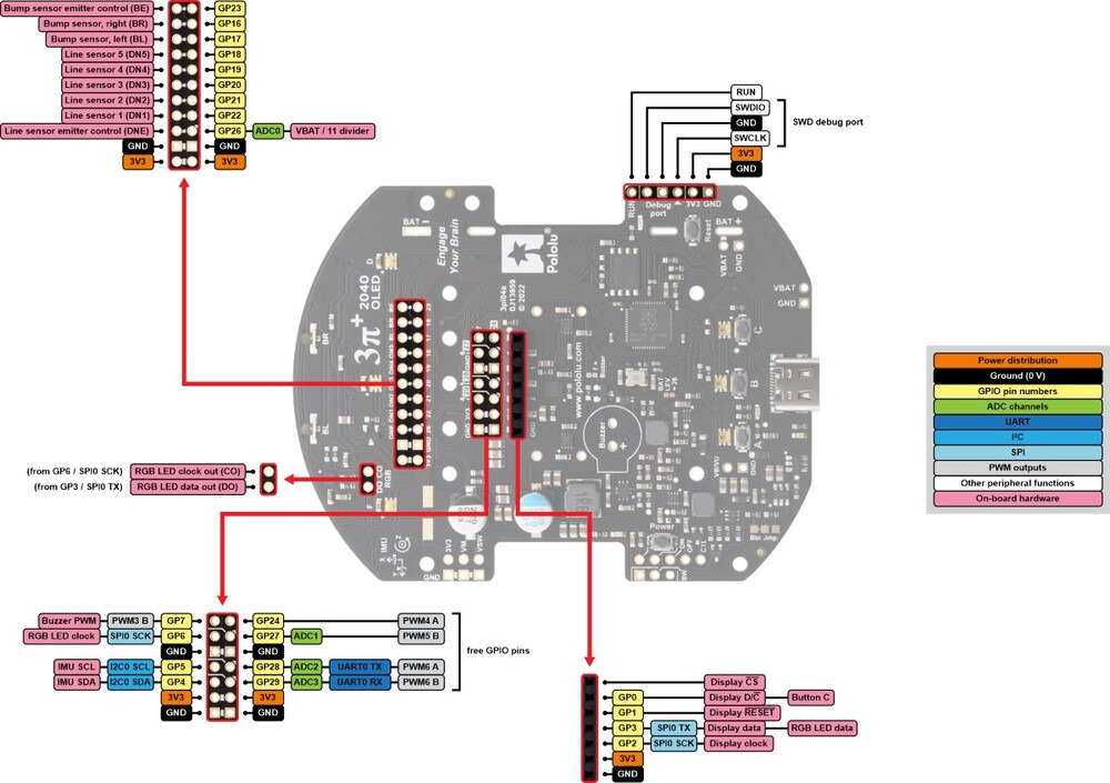
The pins GP24, GP27, GP28, and GP29 are free I/O pins that are not used for anything on the 3pi+ 2040. Each of these pins is accessible on the mid expansion header, and can be used as a general purpose input, digital output, or PWM output. Three of the pins (GP27, GP28, and GP29) can be used as analog inputs.
Software
The robot can be programmed in Python (using MicroPython) or in C. In these lab exercises, we will be programming in C to gain more direct experience with the boundary between software and hardware. The robot runs no operating system, so when you load a C program onto it, that is the only software running.
As is typical in embedded software development, the software you will write will depend on one or more layers of toolkits provided by the various companies involved in the product:
- The lowest level is the ARM Cortex-M0+ instruction set, which you will not use directly in these labs. To use it directly, you would write your code in the ARMv6 assembly language.
- The next level is to use the C language together with a cross compiler provided by ARM, Ltd. A cross compiler is a compiler that runs on a host machine (a Windows, Mac, or Linux machine) and produces machine code to be loaded onto the microcontroller. Writing programs in C is much easier than in assembly language.
- The Raspberry Pi Pico SDK is a collection of C functions designed for use with the RP2040 on the Pico board. Although the robot is not identical to the Pico board, many of these C functions work unchanged with the robot. Moreover, the develpment toolchain we will use is the same (cmake for building and picotool for loading onto the processor).
- The Robot library provided by Pololu provides additional C functions that are customized to the particular board design on the robot. These functions provide convenient interfaces to the various sensors and actuators on the robot.
- Lingua Franca is a coordination language for designing and composing software components. In these lab exercises, we will use its C target and a small library of pre-defined components called reactors that offer convenient access to certain robot features and examples on which you can base your own code.
- CMake is a build tool that manages dependencies. Nearly any program you build will depend on other programs and libraries and maintaining these dependencies can be very tedious. CMake supports encoding the dependencies in a way that makes it more likely that your code will compile even when put on a different computer or with a different filesystem organization.
Development Tools
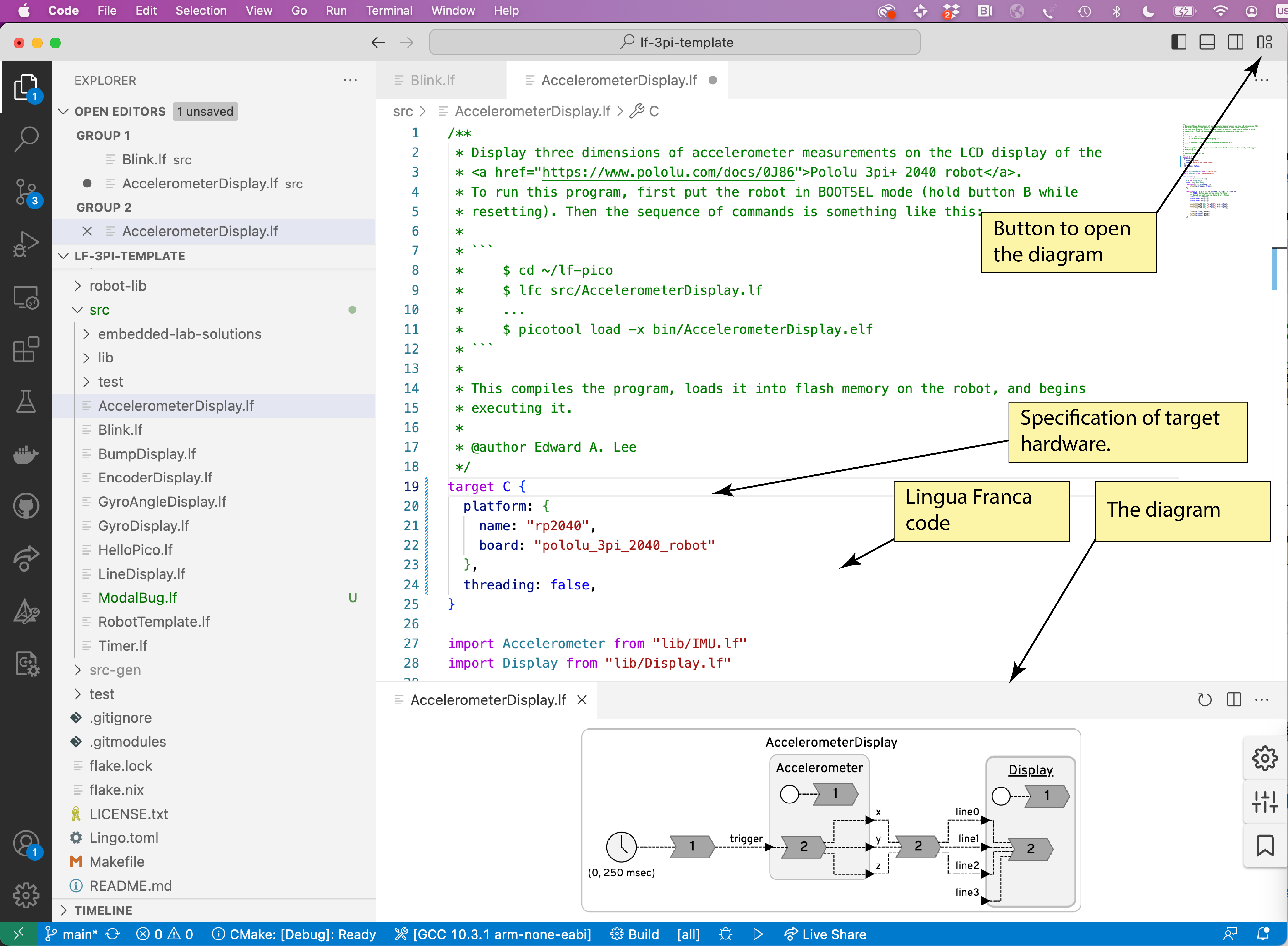
For developing C and Lingua Franca programs, we recommend using Visual Studio Code (VS Code), an integrated development environment (IDE) from Microsoft. Three VS Code extensions will prove particularly useful, the C/C++ extension, the Lingua Franca extension, and CMake Tools, all available from the Visual Studio Marketplace. The VS Code extension for Lingua Franca has a particularly useful feature where it automatically generates a diagram showing the structure of your program, as shown below:
3.1 Prelab
These exercises are intended to make sure you are up-to-speed on using the Unix command line. See Resources for some pointers.
- What flag for
lsdisplays all files, even hidden ones? - How do you move to the parent directory of the current one?
- What is the difference between the
mvandcpcommands? - What does the
-hflag oflsdo? Hint: usemanto find out. - In a git repository, what command displays whether there are any local changes and what they are?
- In a git repository, what does
git pulldo?
3.2 Deploying Example Code
We will now compile and load an example C program onto the robot. We do this two different ways, using the command line and using an IDE.
Important
If you let Nix manage your build environment, you need to always make sure to run
nix developat the root of your repository before using the shell. Besides installing things in the filesystem, it also sets environment variables likePICO_SDK_PATH, which must be set in order to compile code that uses the RPi-Pico SDK.
Ensure that your shell environment is set up correctly by checking that the PICO_SDK_PATH variable points to the root location of the RPi-Pico SDK.
You may wish to look at the README file in that directory.
Check the environment variable by printing it:
$ echo $PICO_SDK_PATH
It should print a path that looks like <path_to_your_repo>/pico-sdk.
If the environment variable PICO_SDK_PATH is not set, simply run nix develop.
Using the Command Line
First, clone the raspberry-pi/pico-examples repository (for example, in your home directory) and make it your current working directory:
$ cd ~
$ git clone https://github.com/raspberrypi/pico-examples.git
$ cd pico-examples
Make a blank build directory and use it to compile all the examples:
$ mkdir build
$ cd build
$ cmake ../
$ make
This should result in a rather lengthy output.
When it finally finishes, each of the subdirectories of the build directory will contain binary files that you can load onto the robot.
Connect the robot to the USB port of your host computer.
Before flashing the binary to your RP2040 based board, the board must be placed into BOOTSEL mode. On the Pololu 3Pi+ robot, hold the B button, press and release RESET, then release the B button.
(On a Raspberry Pi Pico, hold the RESET button while connecting the board to the host.)
You can then use the picotool to load and execute one of the sample programs:
$ picotool load -x blink/blink.elf
The -x option directs the robot to execute the code after loading it.
This will result in an LED blinking on the robot.
The loaded code will persist on the robot until the next time it is put in BOOTSEL mode and loaded with a new program.
You can disconnect the robot and use the power button to start it running on battery power.
Note
When you put the robot in
BOOTSELmode, you should see the OLED display go blank and an external disk appear with a name likeRPI-RP2. You can also deploy theblinkdemo by draggingblink.uf2(in~/pico-examples/build/blink) into theRPI-RP2folder. The robot should immediately start running the program.
Troubleshooting
You may see the following error message reported by
picotool:Device at bus 2, address 5 appears to be a RP2040 device in BOOTSEL mode, but picotool was unable to connect. Maybe try 'sudo' or check your permissions.If you see this message, this means that your user does not have permission to access the RP2040 via USB. You can add
udevrules to allow regular users to access the RP2040, as described here.
For WSL users,usbipdneeds to be installed and used with Windows PowerShell as an administrator. Please check here for more details.
Using VS Code
Next we will repeat the exercise, but this time using VS Code rather than the command line to compile the code. Under the hood, VS Code uses the CMake Tools extension to achieve the same process.
Start VS Code in your root pico-examples directory:
$ cd ~/pico-examples
$ nix develop
$ code .
(The second line may not be necessary if you have already done this.)
This will likely result in a popup appearing as follows:
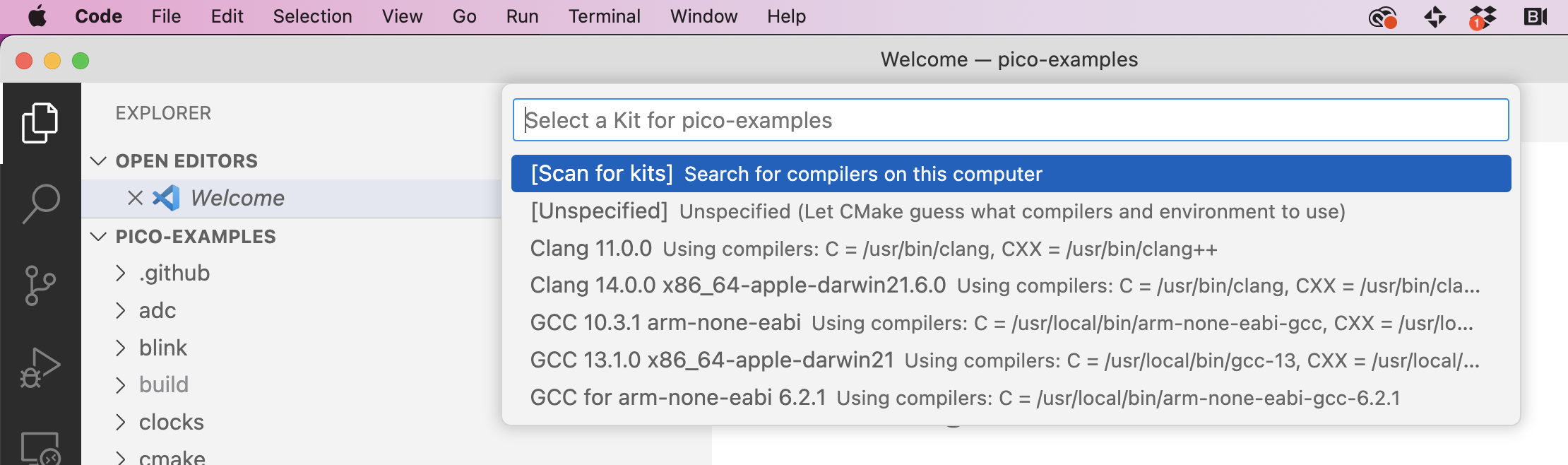
You should select the arm-none-eabi kit. If you do not see one, select "Scan for kits". It you do not see the popup above, click on "No kit selected" on bottom bar. NOTE: You may need to make sure that CMake Tools is the Configuration Provider. Select View > Command Palette in the menu (or use the keyboard shortcut Shift + Ctrl + P on Linux/Windows; Shift + Cmd + P on a Mac) and begin typing C/C++ Change Configuration Provider until you see this:
NOTE You may need to make sure that CMake Tools is the Configuration Provider. Select View > Command Palette in the menu and begin typing C/C++ Change Configuration Provider until you see this:
If CMake Tools is not available, then the cmake extension is not installed in VS Code.
Note for VM users If you are using the VM image, click on "No kit selected" and you should be able to find the
arm-non-eabikit in the drop-down menu. You might also be unable to find theCMake Tools (active)as above, but compilation should still work.
If all goes well, VS Code will have configured and generated all the build files, and you see output something like this:
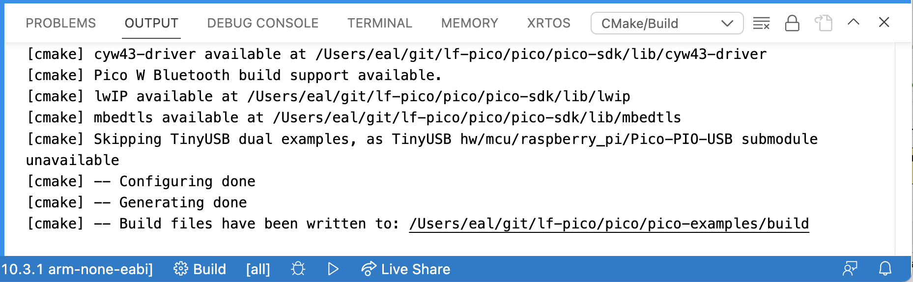
VS Code has run CMake, but it has not yet compiled the example programs. To compile them, click on the "Build" button in the blue bar at the bottom. If you already ran the build on the command line as above, then this time it should not take too long.
When you see "Build finished with exit code 0," then you can load the code onto the robot using picotool. To do this from within VS Code, select the Terminal tab in the Output subwindow and issue the load command as above:
$ picotool load -x build/blink/blink.elf
Make sure the robot is in BOOTSEL mode before doing this.
Examining the C Program
Find and examine the C program blink.c. How is it controlling the timing of the blinking of the LED?
Checkoff: Verify that the VS Code and command-line mechanisms are working. Explain how the timing of the blinking of the LED is controlled.
3.3 A First Lingua Franca Program
Start code in the root of your repository based on lf-3pi-template (see Getting Started):
$ cd ~/my-rpi3
$ code .
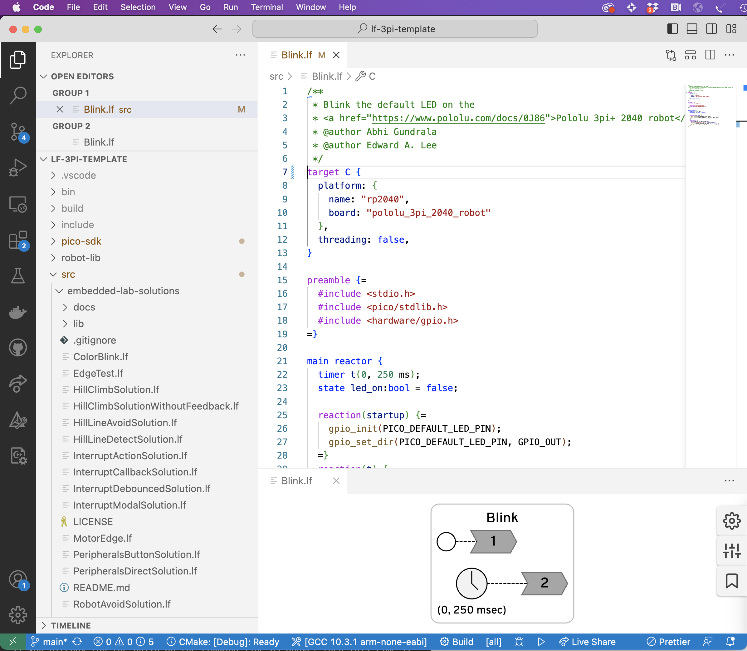
Open and examine the Blink.lf program in the src directory. You may want to open the diagram and drag its window pane to the bottom so that you see something like this:
To compile this program, use Ctrl + Shift + P and select the option Lingua Franca: Build (start typing until auto-complete finds it). On a Mac, use the Cmd key instead of Ctrl.
Alternatively, you could use lfc to invoke the compiler from the command line. You can do this from a terminal outside VS Code, or by selecting View > Terminal from the menu, and typing:
$ lfc src/Blink.lf
Connect your robot in BOOTSEL mode and load and execute the program:
$ picotool load -x bin/Blink.elf
You should see same blinking LED as before.
Now, examine the LF program. How is the timing of the LED controlled here? You may want to consult the Lingua Franca documentation for timers.
Modify the Blink.lf program to use two timers, one that turns on the LED and one that turns it off, eliminating the state variable led_on.
Put your modified program in a file called ToolsBlinkSolution.lf.
Checkoff: Show your modified LF program. Explain how this use of timers is different from the sleep function used in the C code blink.c.
3.4 Printing Output
As is typical of embedded platforms, the Pololu robot does not normally have a terminal connected to it. The LEDs and small LCD display can be used to get information about the running program, but often, particularly while debugging, it is convenient to be able to simply insert printf statements into your programs to see what is going on.
Your first task here is to modify your previous LED blinker to print "ON" and "OFF" each time it turns on or off the LED.
Please put your modified program in a file called ToolsPrintfSolution.lf.
If you run the program as above, however, where do these printed statements go?
The C function printf sends textual data to a conceptual device called stdout (for "standard output").
By default, the robot is configured to direct all stdout text to a serial port on its USB interface.
The trick, therefore, is to get your host computer to connect to that serial port and display data that arrives from the robot.
To do that, we use a terminal emulator called screen. But first, we have to identify the serial port device that was created when the program started up.
Finding the device on macOS
On macOS, the device is likely to appear in the /dev directory on your computer under a name that includes "usb" in its name, which you can look up as follows:
$ ls /dev/*usb*
The output may look like this, listing both a "callin" device /dev/tty.usb* and a "callout" device /dev/cu.usb* (for more information, see StackOverflow):
/dev/cu.usbmodem14201 /dev/tty.usbmodem14201
Finding the device on Linux
On Linux, the device is likely to appear in the /dev directory under a name that starts with ttyACM, which you can look up as follows:
$ ls /dev/ttyACM*
Note for VM users
ttyACM\*cannot be found when Pololu is in BOOTSEL mode. To find it, pressRESET, choose the USB device (in VirtualBox:Device->USB->Raspberry Pi RP2 Boot), and you should be able to see it under/dev.
Using screen
To use screen, we specify a device (e.g., /dev/ttyACM0) and a baud rate, as follows:
$ screen <device> 115200
You should now see the printed outputs. You can return terminal to normal mode by detaching screen by typing Ctrl + a followed by d. You can reattach with:
$ screen -r
To permanently end screen, type Control-A k (for kill).
If screen immediately exits with the message [screen is terminating], you might need to execute it with root rights.
Checkoff: Show ON-OFF output.
3.5 Modular Reusable Reactors
The LED code in Blink.lf is in a main reactor, which cannot be imported into any other Lingua Franca application.
Your next task is to create reusable reactor called LED that has a single input named set with type bool.
When the reactor receives an input event with value true, it should turn on the LED.
When it receives an input with value false, it should turn off the LED.
To do this, create a file in your src/lib directory called LED.lf with the following structure:
target C {
  platform: {
    name: "rp2040",
    board: "pololu_3pi_2040_robot"
  },
  single-threaded: true
}
preamble {=
  #include <hardware/gpio.h>
=}
reactor LED {
  input set:bool;

  reaction(startup) {=
    // Fill in your code here
  =}

  reaction(set) {=
    // Fill in your code here
  =}
}
Then create a new LF file called ToolsLEDSolution.lf that imports this reactor and drives its input in such a way as to blink the LED. The following LF documentation could prove useful:
You have probably noticed some patterns here. E.g., each LF file begins with this:
target C {
  platform: {
    name: "rp2040",
    board: "pololu_3pi_2040_robot"
  },
  single-threaded: true,
}
This specifies that the target language is C, so the lfc compiler generates C programs. The platform specification indicates that the C runtime system for the Raspberry Pi 2040 should be used and that the target board is the Pololu robot. The single-threaded directive indicates that the target is bare metal machine with no operating system and no thread library.
To initialize and toggle the LED, we are using library functions like gpio_put which are declared in a header file gpio.h that is part of the standard Pico SDK.
Inclusion of this header file is a consequence of this directive:
preamble {=
  #include <hardware/gpio.h>
=}
What happens if you omit this?
For documentation about this header file, see the Pico SDK documentation, and specifically the hardware_gpio section.
These functions manipulate memory-mapped registers that control the GPIO pins of the processor.
On the robot, one of those pins, identified in the header files by the PICO_DEFAULT_LED_PIN macro, controls the LED you see blinking.
Subsequent labs will explore more deeply the use memory-mapped registers for I/O.
Checkoff: Show and explain how your program works.
3.6 Postlab Questions
-
What format specifier(s) for
printfallows the printing of floats (there may be several)? -
When might
printfstatements be the best tool for debugging? -
What other tools might be useful for debugging embedded software (note that using an interactive debugger like
gdbwith the robot or Pico board is possible but requires extra hardware)? -
What does the
volatilekeyword mean in C and when might you use it? -
What were your takeaways from the lab? What did you learn during the lab? Did any results in the lab surprise you?