4. Interfacing with Sensors
The purpose of this exercise is to learn to read sensor values on a microcontroller and to interpret those values. You will read accelerometer data from a device on the Pololu robot, convert the readings to meaningful units, and use the results to estimate the tilt of the surface on which the robot sits. As a side effect, you will gain experience reading a technical datasheet.
The Pololu robot includes an inertial measurement unit (IMU) made by ST Microelectronics, part number LMS6DSO, which includes an accelerometer and a gyroscope. In this lab, we will focus on the accelerometer.
On the robot, the IMU is connected to the RPi via the I2C bus, a serial communication bus that is widely used to connect lower speed peripheral chips to microprocessor chips.
Part of the purpose of this exercise is to learn to work from incomplete documentation, an inevitable reality in any engineering project. It takes a certain amount of detective work to identify properties of the hardware you are working with that may be important in your application.
4.1 Prelab
References
- Chapter 7, Sensors and Actuators, of Lee and Seshia
- ST LMS6DSO inertial module datasheet
Questions
-
Reading a datasheet.
-
The output data rate (ODR) is determined by a register on the IMU chip called
CTRL1_XL. On the Pololu robot, theCTRL1_XLregister is set to hexadecimal value 0x30 (0b00110000 in binary) during initialization of the robot (by writing to the I2C bus). What is the ODR rate that this specifies?Hint: Section 9.12 of the inertial module datasheet describes the
CTRL1_XLaccelerometer control register. -
The accelerometer on the robot can be configured to have one of four ranges by setting the
CTRL1_XLregister. Each range is a multiple of g, the acceleration due to gravity at the earth's surface, defined to be 9.80665 m/s2. What are the ranges supported by the accelerometer on the IMU chip? -
The robot software configures the accelerometer hardware to use one of these four ranges during initialization. What is this range?
-
The IMU chip offers an optional low pass filter (LPF) that performs additional smoothing of the signal from the accelerometer at the cost of additional latency. By default, the robot initializes the IMU to not use this filter. What value would you set the
CTRL1_XLregister to to use the filter and leave the ODR and range as above?
-
-
Interpreting sensor data
-
According to table 2 of the inertial module datasheet, with the default range, the sensitivity of the accelerometer is 0.061 mg/LSB. Here, mg stands for milli-g's and LSB for least significant bit. The accelerometer has a 16-bit analog to digital converter (ADC). Reading its raw data over the I2C bus yields a 16-bit signed integer. Explain where the number 0.061 comes from.
Note: The
robot-liblibrary provides a convenience functionimu_read_accthat reads accelerometer data into an array of floats, which it converts into units of g. Hence, when using this library, you will not need to deal with the complexities of interpreting the raw binary output of the accelerometer. But understanding the sensitivity is still important. -
As explained in Chapter 7, Sensors and Actuators, of Lee and Seshia, a sensor output may be modeled by an affine function f(x) = ax + b, where a is the sensitivity and b is the bias. For this IMU, ideally, if x is the 16 bit integer received over the I2C bus, a = 0.000061, and b = 0, then f(x) is the acceleration in g's. But both a and b may vary with temperature. How much variation in a should you expect (in percent per degree centigrade)? How much bias can you expect (in mg)? How much should you expect the bias to change with temperature (in mg per degree centigrade)?
Hint: Table 2 could be helpful. Bias is referred to as "zero-g level" in this table.
-
4.2 Sampling an Accelerometer
The goal of this lab is to calculate and display the inclination of the Pololu robot. The inclination is the amount of tilt of the surface on which the robot sits. Chapter 2 of Lee and Seshia describes the orientation of a vehicle in terms of pitch, roll, and yaw, illustrated as follows:
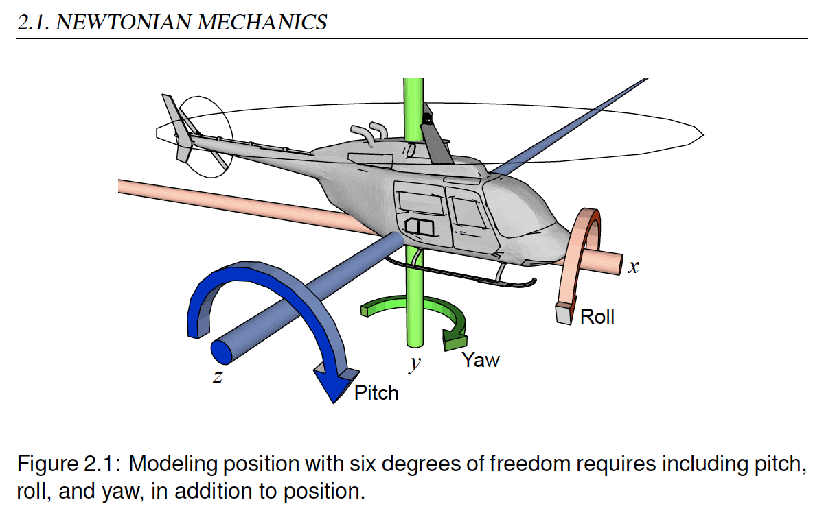
Our goal will to just measure pitch and roll because we will assume that the robot always sits right-side-up on a reasonably level surface. Our goal will be to measure relatively small deviations from level.
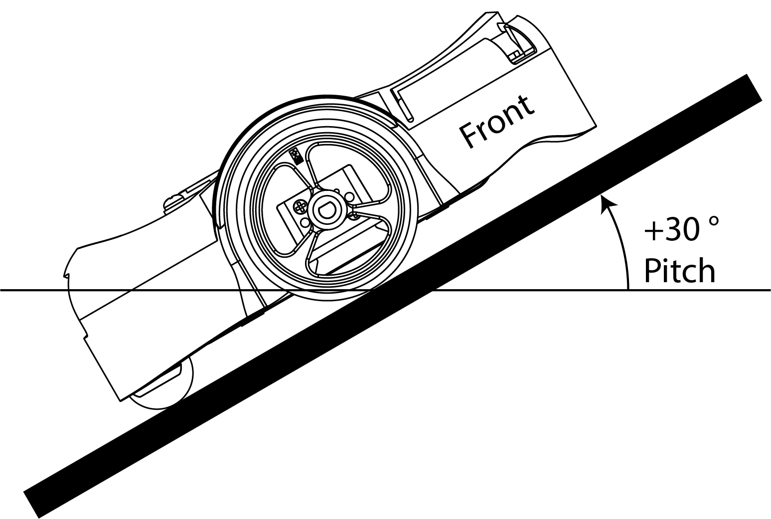
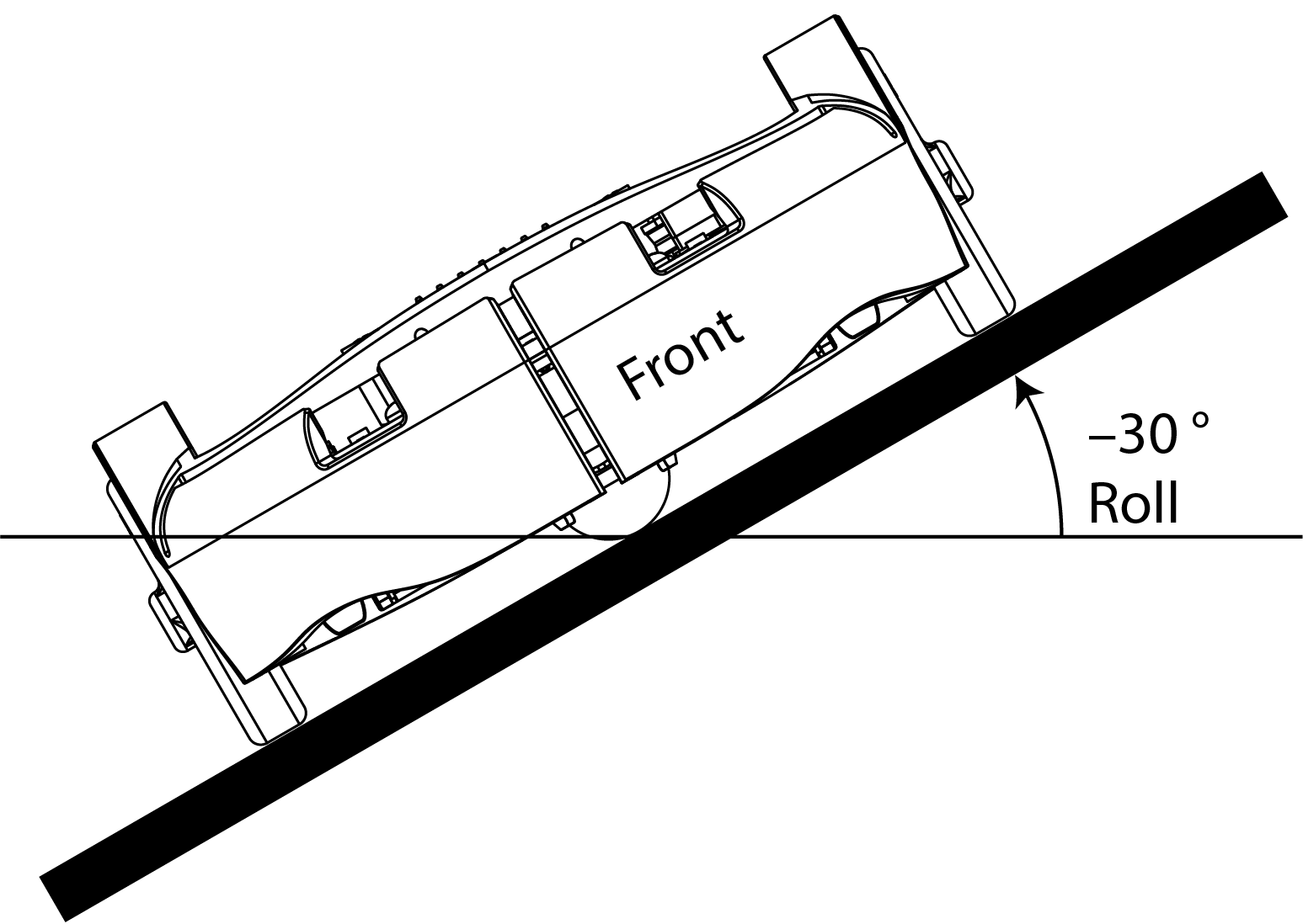
Pitch is the angle deviation from horizontal of a straight line coming out of the front of the robot. Roll is the angle deviation from horizontal of a straight line going directly through the wheels. These are illustrated in the following figures:
Note: An accelerometer cannot measure yaw because Earth's gravity acts in the same direction as the Z-axis, which prevents the accelerometer from measuring rotation on the Z-axis. Instead, a different sensor called a magnetometer (i.e., digital compass) could be used to measure yaw by measuring an object's orientation relative to Earth's magnetic north pole. (Reference: IoT Code Guidebook - Accelerometer)
It is a simple geometry problem to figure out how to calculate these two angles from accelerometer measurements. But if you are rusty on your geometry, you could consult page 7 of Using an Accelerometer for Inclination Sensing, by Christopher J. Fisher.
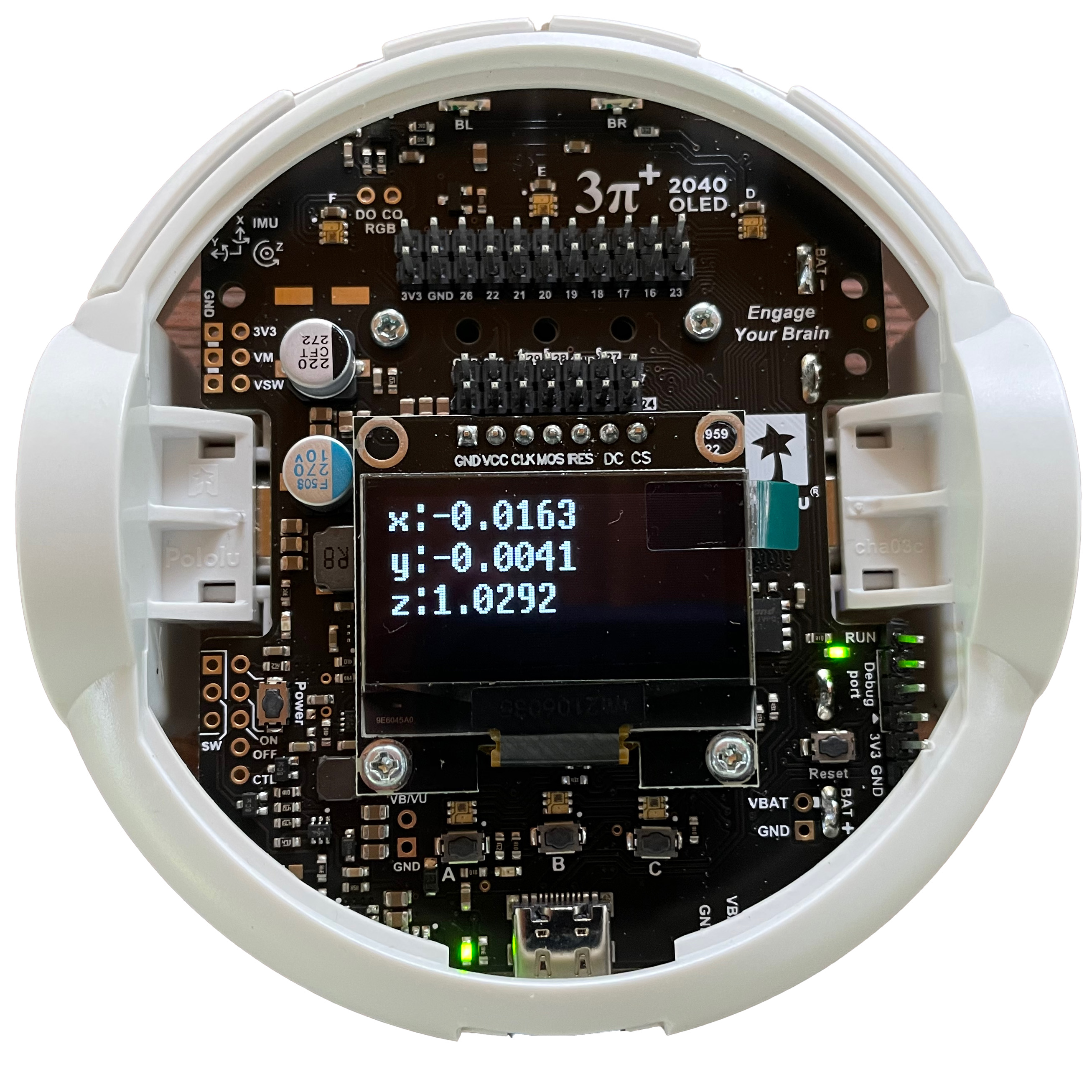
To help you get started, a sample Lingua Franca program AccelerometerDisplay.lf is provided. To try out the program, plug your robot into the USB port of your host computer and put it in BOOTSEL mode by holding the B button while pressing the reset button. In the root directory of your clone of the lf-pico repo, compile and load the program onto the robot:
$ lfc src/AccelerometerDisplay.lf
$ picotool load -x bin/AccelerometerDisplay.elf
You should see the display light up looking something like this:
-
Interpreting the numbers
- Explain why, when the robot is sitting on a flat surface, the sensed accelerations in the x and y directions are near zero and in the z direction near one.
- Why is the z direction not near negative one? Doesn't gravitation pull you down, not up?
Experiment with rotating the robot and observing how the three measured accelerations change.
CHECKOFF: Demonstrate the app working on all three axes.
-
Examine the LF program
-
Open the file
src/AccelerometerDisplay.lfin VS Code. Enable the diagram, navigate and read the code, and explain what each of the reactions labeled A, B, C, and D does: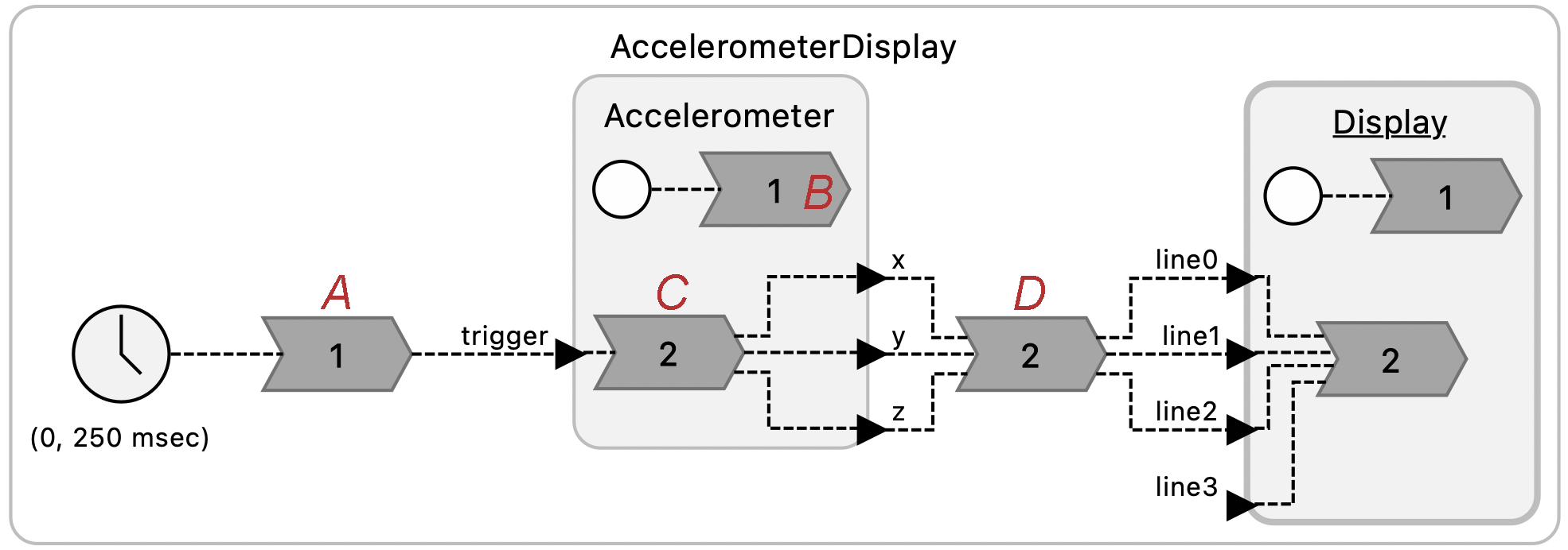
-
Notice the
targetspecification at the top of each of the .lf files. What do you think is the significance of the directive:single-threaded: true
CHECKOFF: Explain what the four reactions do and the importance of single-threaded being turned on.
-
4.3 Measuring Tilt
Create a reactor called Tilt that takes as inputs the x, y, and z readings from the accelerometer and outputs the pitch and roll in degrees. Save the file's name as Tilt.lf, and put this file in the src/lib directory and then use it in a variant of the AccelerometerDisplay.lf named SensorsTiltSolution.lf, to show pitch and roll in degrees rather than g force accelerations in the LCD display. Save your Tilt.lf file and Tilt reactor for use in future labs.
CHECKOFF: Show your pitch and roll displays and check that they are reasonable.
4.4 Postlab Questions
-
Suppose a sensor gives you a 16-bit signed integer representing some measured quantity in some well-defined units, that the range of the sensor in those units is -4.0 to 4.0, and that the sensitivity in those units is 0.000122 (1/213). What is representation in hex and in binary of a sensor reading of 1.0 in those units?
-
Suppose that your goal with the accelerometer is to measure the tilt in degrees of the surface on which your robot is moving. How would you measure the bias and then compensate for this bias?
-
Suppose that your goal is to orient the robot to point straight up the hill. How would you use the pitch and roll measurements to accomplish this?
-
What were your takeaways from the lab? What did you learn during the lab? Did any results in the lab surprise you?